background image

Ŷ

 chapter 2 bios setup and security feature


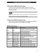
Entering the BIOS Setup Screen 

First, turn on the power. When the BIOS performs the POST 
(Power-On Self Test), press the F2 key quickly to activate the AMI 
BIOS Setup Utility. 


Note:

 You may need to press the F2 key fairly quickly. Once the system begins to load 

Windows, you may have to retry by cycle-power on again. 


Leaving the BIOS Setup Screen 

When you have finished modifying the BIOS settings, exit the BIOS. It 
takes a few seconds to record changes in the CMOS. 


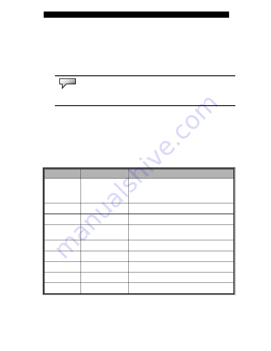
BIOS Action Keys


Function Key  Command 

Description 

ESC Exit 

Leaves a sub-menu to return to the 
previous menu OR exits the BIOS setup 
while saving changes. 

Enter 

Go to Sub Screen 

Shows the Sub Menu 

F1 

General Help 

Shows the Help Screen  

F10 

Save and Exit 

Saves changes and reboots the 
computer. 

<Tab> 

Select a field 

Selects the next field. 


Select an item 

Selects the next upper item. 


Select an item 

Selects the next lower item. 

Lower value 

Selects the next value within a field. 

Higher value 

Selects the next value within a field. 


2-3 

Summary of Contents for Area-51 m5500

Page 1: ...i 1...

Page 2: ...ed trademarks of Microsoft Corporation DOS and Windows 95 98 ME 2000 NT XP VISTA are trademarks of Microsoft Corporation Product names mentioned herein may be trademarks and or registered trademarks o...

Page 3: ...atus Indicators 1 15 Keyboard Features 1 16 Function Quick Keys 1 16 Windows Keys 1 17 Embedded Numeric Keypad 1 17 Touchpad 1 18 Graphics Subsystem 1 19 Adjusting the Display Brightness 1 19 Extendin...

Page 4: ...Prolonging the Battery s Life and Usage Cycles 3 6 Using Windows Power Options 3 7 Windows Power Schemes 3 7 8 Suspend Modes 3 9 10 Power Button Action 3 11 Low Battery Warning 3 12 Power Manual Quic...

Page 5: ...ems 5 12 Network Adapter Ethernet Problems 5 13 PC Card PCMCIA Problems 5 14 Performance Problems 5 15 Firewire IEEE1394 and USB2 0 Problems 5 16 APPENDIX A Product Specification APPENDIX B Agency Reg...

Page 6: ...the and symbols are used For instance Start Settings Control Panel Display means clicking the Start icon first then the Settings then the Control Panel then the Display icon When you need to make a se...

Page 7: ...omputer to adverse shock and vibration Do not expose the computer to dust and dirt Do not place objects on top of the computer in order to avoid damaging the computer Do not place the computer on rock...

Page 8: ...computer and remove the battery pack 2 Disconnect the AC adapter 3 Use a soft cloth dampened with water Do not use liquid or aerosol cleaners Contact tech support or see your service technician if any...

Page 9: ...rovided by the BIOS Chapter 3 Battery Power Power Management In this chapter you will learn the fundamentals of power management and how to use them to achieve longer battery life Chapter 4 Upgrading...

Page 10: ......

Page 11: ...chapter 1 getting to know the basics 1 1 C H A P T E R O N E GETTING TO KNOW THE BASICS This chapter introduces the features and components of the computer...

Page 12: ...needs higher performance or lower battery consumption Both graphic engines are DirectX 9 compatible LCD Display The computer is equipped with a wide 15 4 TFT high resolution display panel for clear t...

Page 13: ...to connect to any USB based peripheral devices Wireless LAN The internal wireless LAN module allows your notebook to connect wirelessly to other 802 11 enabled systems devices or networks Internal US...

Page 14: ...1 LCD Latch The LCD latches lock unlock the LCD panel 2 Built in Microphone The built in microphone records sound 3 LCD Display This panel is where the system content is displayed The LCD panel has a...

Page 15: ...tus of these functions Numeric keypad cap lock scroll lock WLAN module enabling and disabling and also the ODD HDD activities See the LED Status Indicator Section for details The LED Status indicators...

Page 16: ...le the wireless function If the WLAN function is enabled the WLAN LED turns green otherwise the WLAN LED is dark 10 Instant On Multimedia Player Launch Key When the system is powered off pressing the...

Page 17: ...pack is a built in power source for the notebook 3 Kensington Lock Key Hole A Kensington type security lock latches to this keyhole for anti theft purposes 4 4 in 1 Card Reader The 4 in 1 card reader...

Page 18: ...you leave the switch in the ON position the computer will boot to the external graphic engine NVIDIA GeForce Go 6600 which has higher performance and higher power consumption If you leave the switch i...

Page 19: ...Grill The fan grill is where air is exchanged to dissipate the internal heat Do not block this airway completely 6 Firewire IEEE1394 1394a Port This is a high speed serial data port You may connect an...

Page 20: ...chapter 1 getting to know the basics Bottom View 1 Battery Pack and Battery Latch The battery pack is a built in power source for the notebook Slide the battery latch to release the battery pack 1 10...

Page 21: ...a HDD upgrade 4 System Device Cover The system s processor with cooler assembly wireless LAN module and DDR memory module are located under the case cover You may install the WLAN module and the syste...

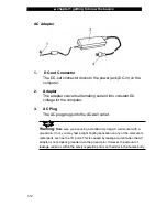
Page 22: ...e AC plug plugs into the AC wall outlet 1 12 Warning Make sure you are using a standard 3 prong AC wall socket with a ground pin If not you may feel a slight tingling sensation on any of the computer...

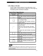
Page 23: ...s the Silent mode is active Blinking blue light indicates the battery is being charged Blinking red light indicates the battery power is low when the system is turned ON Persistent blue light indicate...

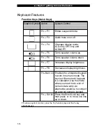
Page 24: ...e down Fn F7 Increases display brightness Fn F8 Decreases display brightness Fn Num Lk Enables the embedded keypad to work in numeric mode The keys act like numeric keypads in a calculator Use this mo...

Page 25: ...on Menu Key This key brings up the popup menu for the application similar to a click of the right mouse button Embedded Numeric Keypad Press Fn NumLk to enable the embedded numeric keypad The numbers...

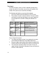
Page 26: ...utton Equivalent Tapping Action Execution Click twice quickly Tap twice at the same speed as double clicking the mouse button Selection Click once Tap once Drag Click and hold to drag the cursor Tap t...

Page 27: ...are DirectX 9 compatible Adjusting the Display Brightness The notebook uses special key combinations called hot keys to control brightness Press Fn F7 to increase the brightness Press Fn F8 to decreas...

Page 28: ...lift up the lid Then tilt it to a comfortable viewing position The LCD panel has a maximum opening of 135 degrees Do not push it down forcibly To close the display cover fold it down gently until the...

Page 29: ...ting the Audio Volume in Windows 1 Click the speaker symbol in the task tray in Windows 2 Drag the volume control bar up or down to adjust the volume 3 To temporarily silence the speaker without chang...

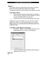
Page 30: ...included EMI CORE to the phone line 2 Plug the other end of the line into the analog phone wall outlet Depending on where your computer is used you may need to change settings in the modem The correc...

Page 31: ...le into the network connector until the connector snaps securely into the receptacle 2 Connect the other end of the cable to either an RJ 45 jack wall outlet or to an RJ 45 port on a UTP concentrator...

Page 32: ......

Page 33: ...ature 2 1 C H A P T E R T W O BIOS SETUP AND SECURITY FEATURE In this chapter you will learn how to enter the BIOS Setup Menu and manipulate various hardware control settings You will also learn how t...

Page 34: ...the computer s standard operations However there are occasions when you may be required to modify the default settings in the BIOS For example you may need to configure the BIOS power management APM...

Page 35: ...ng the BIOS settings exit the BIOS It takes a few seconds to record changes in the CMOS BIOS Action Keys Function Key Command Description ESC Exit Leaves a sub menu to return to the previous menu OR e...

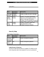
Page 36: ...Sub menu Description Date N A Type in the current date in MM DD YY format Time N A Type in the current date in HH MM SS format Advanced Setup IDE Configuration Item Selections Sub menu Description Pr...

Page 37: ...ness remains the same whether or not AC power is present BIOS Post Beep Sound Enable Disable Enable The system beeps when performing POST on boot Disable The beep is disabled Security Setup Boot Setti...

Page 38: ...be sent back to the factory or to an authorized service dealer to reset the passwords Power Setup Item Selections Sub menu Description Power Button Mode On Off Suspend On Off When the power button is...

Page 39: ...essages When disabled the system will display POST messages i e device information Boot Device Priority Item Selections Sub menu Description 1st Boot Device Set the type of device for the 1st drive BI...

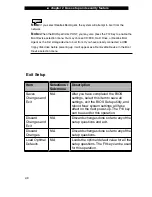
Page 40: ...e in the Boot Device selection menu Exit Setup Item Selections Sub menu Description Saves Changes and Exit N A After you have completed the BIOS settings select this item to save all settings exit the...

Page 41: ...3 battery power power management 3 1 C H A P T E R T H R E E BATTERY POWER POWER MANAGEMENT In this chapter you will learn the fundamentals of power management and how to use it to achieve longer batt...

Page 42: ...the system turn off its display after 2 minutes of inactivity to save power Efficient power management can help you work longer sessions before having to recharge the battery The Battery Pack Lithium...

Page 43: ...tery condition occurs when battery power is reduced to 3 The red battery status LED indicator will blink and the system will beep at 4 second intervals When the notebook warns you of its low battery c...

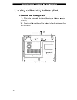
Page 44: ...ower management Installing and Removing the Battery Pack To Remove the Battery Pack 1 Place the notebook bottom side up on a flat and secure surface 2 Push the latch and pull the battery s hard case a...

Page 45: ...the notebook plug the AC adapter into the notebook and an electrical outlet The charging time is approximately 4 6 hours when the notebook is turned off and approximately 6 10 hours when the notebook...

Page 46: ...Store the battery pack at room temperature Higher temperatures tend to deplete the battery s power faster Make good use of the power management function The Save To Disk Hibernate option saves the mo...

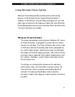
Page 47: ...er Schemes is designed to provide the user with an easy to use interface The Power Schemes tab can be found in the Power Options Properties panel that is accessible via the control panel window Scheme...

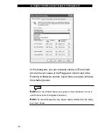
Page 48: ...in the Plugged in column and in the Running on Batteries column Lower time out values will save more battery power Note Also consult the Windows user guide for more information on how to use Windows...

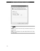
Page 49: ...ystem states and contents are saved to the hard disk drive after a period of inactivity defined by the user No power or very little power is drawn from the battery module under this mode However depen...

Page 50: ...attery power power management Note Do not install or remove the memory module when the system is in the suspend mode Note The actual dialogue box may appear slightly different than the dialog box show...

Page 51: ...ed tab In the pull down menu select how you wish the power button to work Note The actual dialogue box may appear slightly different than the dialog box shown above Warning In the When I close the lid...

Page 52: ...e Alarms tab in the Power Options Properties box If you wish to hear audible beeps click on the Alarm Action button and put a check on Sound Alarm Note Consult the Windows user guide for more informat...

Page 53: ...con at the lower right hand corner of the task bar If you do not see a battery or AC in icon go to the Power Options Properties box and click on the Advanced tab Check off Always show icon on the task...

Page 54: ......

Page 55: ...upgrading your computer 4 1 C H A P T E R F O U R UPGRADING YOUR COMPUTER In this chapter you will learn how to upgrade the DRAM and hard disk drive as well as how to install the optional wireless LA...

Page 56: ...your notebook uses Be sure to make a backup copy of all your data before attempting this operation 4 2 Warning A hard drive upgrade is a delicate process Please observe the following instructions car...

Page 57: ...Unhook the AC cord and all cables devices attached to the notebook Remove the battery 2 Place your hand on a large metal object momentarily to discharge any static electricity 3 Locate and remove Scr...

Page 58: ...metal cases 7 Re attach the metal cases to the new hard drive and tighten the 4 Screw B s Note that the green PC board of the hard disk drive is facing up 8 Re attach the HDD module to the HDD connec...

Page 59: ...chapter 4 upgrading your computer 4 5 When you boot up the PC you may need to create a primary HDD partition reformat the new drive and re install the O S drivers and all necessary applications...

Page 60: ...order to find out what type of DDR module the system uses you need to reboot the system The initial boot message shows you what type of DDR SDRAM module your notebook uses 4 6 Warning A memory upgrad...

Page 61: ...bles devices attached to the notebook Remove the battery 2 Place your hand on a large metal object momentarily to discharge any static electricity Place the notebook on a flat surface and fully close...

Page 62: ...o an angle of 30 degrees see diagram below Pull the DIMM module out of the memory socket Store away the DIMM for future use 6 Install the new DIMM module into the memory socket The DIMM will only fit...

Page 63: ...into place Note Notice the notch on the DIMM The notches should fit nicely with the socket 8 Put the system device cover back and tighten the 9 Screw C s Congratulations You have just completed the m...

Page 64: ...g your computer Note Your computer has been tested with a wide range of DIMM on the market However not all memory modules are compatible Check with your system vendor for a list of compatible DIMM for...

Page 65: ...bout the availability of the mini PCI card 4 11 Warning Installing a mini PCI card is a delicate process Please observe the following instructions carefully or have a qualified technician install it f...

Page 66: ...the small notch in the module with the socket on the connector and insert the card at an angle of approximately 30 degrees into the empty socket Then press it firmly so that the contact edge is driven...

Page 67: ...ard into the socket 4 Put the system device cover back and tighten the 9 Screw C s Congratulations You have now completed the mini PCI card installation During the next time the system boots to Window...

Page 68: ......

Page 69: ...chapter 5 troubleshooting 5 1 C H A P T E R F I V E TROUBLESHOOTING In this chapter you will learn how to solve common hardware and software problems...

Page 70: ...tions If the error continues contact your tech support for service information Before taking further actions consider the following suggestions Check to see if the problem persists when all the extern...

Page 71: ...ted to the system it is usually due to a problem with the device itself Consult the device s manufacturer first Some software programs which have not gone through rigorous coding and testing may cause...

Page 72: ...ol Panel and double click the sounds and audio devices icon In the Audio page make sure that Realtek HD Audio is the default playback device Sound cannot be recorded Double click the speaker icon on t...

Page 73: ...ible If your computer has been subjected to static electricity or physical shock you may have damaged the disk drive The hard drive is making abnormal whining noises You should back up your files as s...

Page 74: ...for a period the files may be fragmented Go to Start Programs Accessories System Tools Disk Defragmenter to perform a disk defragmentation This operation may take a while Interrupt requests or problem...

Page 75: ...isk is firmly seated onto the spindle The disk is damaged or not readable The disk cannot be ejected Normally it takes a few seconds to eject the disk If the disk cannot be ejected it may be mechanica...

Page 76: ...e energy in these modes The screen is difficult to read The display resolution should be set to at least 1024x768 for optimal viewing 1 Go to Start Settings Control Panel and double click the display...

Page 77: ...cepts no input If you are connecting an external keyboard to the system the built in keyboard may not work Try restarting the system The characters on the screen repeat while I type You may be holding...

Page 78: ...essage CMOS Checksum Failure appears during the booting procedure even after rebooting it may indicate failure of the CMOS battery If so you need to replace the battery This battery normally lasts two...

Page 79: ...he memory module may not be installed properly Go back to Chapter 4 to review the details of this operation The memory module may be defective The O S issues an insufficient memory error message durin...

Page 80: ...anual for how to handle such problems Make sure the phone line which the computer is connected to is working Connection difficulties Be sure to disable call waiting on the phone line Be sure to have t...

Page 81: ...ice or resource conflict Replace or update the device driver from the factory CD ROM disk or consult the Windows manual for how to solve the resource conflict problem Make sure the physical connection...

Page 82: ...even with the edge of the computer Remove and insert the PC card again Make sure there is no IRQ conflict with the card See Windows online help for solving IRQ conflicts Reboot the computer and see i...

Page 83: ...slows down its CPU clock to protect itself from thermal damage The program appears stopped or runs very slowly Press CTRL ALT DEL to see if an application is still responding Restart the computer Thi...

Page 84: ...entry which reads Texas Instrument OHCI Compliant IEEE 1394 Host Controllers If it does not exist that means that either Windows has not detected the host controller or the device driver has not been...

Page 85: ...appendix A product specification A 1 A P P E N D I X A PRODUCT SPECIFICATION...

Page 86: ...0 controllers integrated 533 MHz Pentium M 400 Celeron M front side bus 400 533 MHz DDR1 DDR2 interface System Memory DDR1 DDR2 SDRAM 333 400 533MHz PC2700 and PC2 3200 4200 compatible 128 256 512MB 2...

Page 87: ...ler Realtek ALC880 DirectSound 3D EAX 1 0 2 0 compatible A3D I3DL2 compatible AC97 V2 3 compatible 7 1 multi channel compatible through S PDIF Supports Azalia standard 2 stereo speakers Modem Intel IC...

Page 88: ...ible Automatic Jam and auto negotiation for flow control Auto Negotiation and Parallel detection for automatic speed selection IEEE 802 3u High performance 32 bit PCI bus master architecture with inte...

Page 89: ...C Card Genesys GL817E Card Reader Single Slot TYPE II hot insertion and removal supported Multimedia Card MMC Secure Digital Card SD Memory Stick MS and MS Pro Card Ports and Connectors One microphone...

Page 90: ...Low battery state with low battery warning beep SmartPower Power Management Smart Battery Compliant low battery warning beep Auto sensing AC in 100 240V DC out 20V 90W BIOS AMI PnP BIOS Power On Self...

Page 91: ...ntal Limits z m5500 Series 358 W x 272 D x 25 9 34 1 H mm z m5500 Series 7 2 lbs 3 27Kg with 15 4 LCD DVD ROM Drive and 6 cell battery pack Operating Temperature 5 to 30o C 41 to 86o F Operating Humid...

Page 92: ......

Page 93: ...appendix B agency regulatory notices B 1 A P P E N D I X B AGENCY REGULATORY NOTICES...

Page 94: ...quipment and the receiver Connect the equipment into an outlet on a circuit different from that to which the receiver is connected Consult the dealer or an experienced radio or television technician f...

Page 95: ...desired operation European Notice Products with the CE Marking comply with both the EMC Directive 89 336 EEC and the Low Voltage Directive 73 23 EEC and R TTE Directive 1999 5 EC issued by the Commiss...

Page 96: ...elow or a replacement AC adapter contact your local dealer U S and Canada The cord set must be UL Listed and CSA Certified or C UL Listed The minimum specifications for the flexible cord are 1 No 18 A...

Page 97: ...st have a current capacity of at least 10 A and a nominal voltage rating of 125 250 VAC CAUTION MODEL M 5500 SERIES IS DESIGNED TO USE WITH THE FOLLOWING AC ADAPTER MODEL ONLY Manufacturer LITE ON ELE...

Page 98: ...C Adapter for charging CAUTION There is a danger of explosion if the battery is incorrectly replaced Replace only with the same or equivalent type recommended by the manufacturer Discard used batterie...

Page 99: ...anufacturer Discard used batteries according to the manufacturer s instructions ATTENTION Il y a danger d xplosion s il y a remplacement incorrect de la batterie Remplacer uniquement avcc unc batterie...

Page 100: ...appendix B agency regulatory notices CAUTION T his part is h ot Be C areful V OR SI CHT Di ese Flach e wird sehr heiss When you see this symbol be careful as this spot may be very hot B 8...

Reviews: