background image

Alienware Area-51 m5550 Technical Reference

5

CHAPTER FOUR
UPGRADING YOUR COMPUTER

In this chapter, you will learn how to upgrade the DRAM and hard disk drive, and how 
to install the optional wireless LAN mini PCI.

m5550-04-2007-techref.indd   56

4/6/2007   12:29:51 PM

Summary of Contents for Area-51 m5550

Page 1: ...stered trademarks of Microsoft Corporation DOS Windows 95 98 ME 2000 NT XP Vista are trademarks of Microsoft Corporation Product names mentioned herein may be trademarks and or registered trademarks o...

Page 2: ...d Rear Views 15 Side Views 17 Bottom View 20 AC Adapter 23 LED Status Indicators 24 Keyboard Features 25 Function Quick Keys 25 Windows Keys 26 Embedded Numeric Keypad 26 Touch Pad 27 Graphics Subsyst...

Page 3: ...Battery Technology 39 Battery Low Power Warning 39 Installing and Removing the Battery Pack 41 Charging the Battery and Charging Time 42 Checking the Battery Level 42 Prolonging the Battery s Life an...

Page 4: ...e System 64 5 TROUBLESHOOTING First Step 67 Audio Problems 68 Hard Disk Problems 69 Optical Drive Problems 71 Display Problems 72 Keyboard and Mouse Problems 73 CMOS Battery Problems 74 Memory Problem...

Page 5: ...and symbols are used For instance Start Settings Control Panel Display means clicking the Start icon first then the Settings then the Control Panel then the Display icon When you need to make a select...

Page 6: ...of taking care of your AC adapter Do not connect the adapter to any devices other than your computer Do not let water get into the adapter Do not block the ventilation airway of the adapter Keep the...

Page 7: ...any of the following occurs Computer has been dropped or the body has been damaged Liquid has been spilled into the computer The computer does not operate normally Cleaning the Ventilation Grills It i...

Page 8: ...ovided by the BIOS Chapter 3 Battery Power Power Management In this chapter you will learn the fundamentals of power management and how to use them to achieve longer battery life Chapter 4 Upgrading Y...

Page 9: ...Alienware Area 51 m5550 Technical Reference CHAPTER ONE GETTING TO KNOW THE BASICS This chapter introduces the features and components of the computer m5550 04 2007 techref indd 9 4 6 2007 12 29 45 PM...

Page 10: ...so adds realism to PC games LCD Display The computer is equipped with a non wide 16 10 15 4 TFT display panel for the best cinematic viewing experience Serial ATA Hard Disk Drive Support on certain mo...

Page 11: ...dth network connection Firewire IEEE1394 1394a and USB2 0 Ports In addition to a full array of built in I O ports the computer offers IEEE1394 for ultra high speed connection to high bandwidth digital...

Page 12: ...0 Technical Reference 12 System At A Glance Top View 1 LCD Latch The LCD latches lock unlock the LCD panel 2 LCD Display The panel is where the system content is displayed m5550 04 2007 techref indd 1...

Page 13: ...ad cap lock scroll lock WLAN module enabling and disabling and also the ODD and HDD activities See the LED Status Indicator Section for details The LED Status indicators also reveal the status of the...

Page 14: ...ts power usage therefore the fan speed is reduced to achieve the lowest operating noise You may need to go to BIOS Setup to enable Silent Mode for this button See Chapter 2 for details 11 Outlook Expr...

Page 15: ...On Off Switch Use the switch to disable or enable the Wireless function 2 Power Jack DC in The DC out jack of the AC Adapter connects here and powers the computer 3 Modem Port This is where you plug...

Page 16: ...Grill The fan grill is where air is exchanged to dissipate the internal heat Do not block this airway 6 Kensington Lock Key Hole A Kensington type security lock latches to this keyhole for anti theft...

Page 17: ...ernatively you may connect the SPDIF output to an external DTS AC3 or PCM sound processor decoder in your home stereo system 3 Microphone Jack The microphone jack 3 5 mm diameter is where you connect...

Page 18: ...ht protected when a DVD movie is played the output is scrambled to prevent analog recording 8 Ethernet LAN Port The port connects to a network hub via the RJ 45 cable and also conforms to 10 100 1000B...

Page 19: ...essCard Slot The slot is where ExpressCard Type 54 is inserted ExpressCard Type 54 allows insertion of 54mm and 34mm cards ExpressCard integrates both the PCI Express bus technology and USB2 0 standar...

Page 20: ...uilt in power source for the notebook Slide the battery latch to release the battery pack 2 Hard Disk Drive Cover The system s hard disk drive is located under the cover The HDD can be upgraded to a l...

Page 21: ...Alienware Area 51 m5550 Technical Reference 21 m5550 04 2007 techref indd 21 4 6 2007 12 29 46 PM...

Page 22: ...AN module and the system memory can be upgraded to a larger capacity See Chapter 4 for instructions on a memory upgrade 4 Ventilation Grill The fan grill is where air is exchanged to dissipate the int...

Page 23: ...o the AC wall outlet Warning Make sure you are using a standard 3 prong AC wall socket with a ground pin If not you may feel a slight tingling sensation on any of the computer s metal parts such as th...

Page 24: ...icates the notebook is in Suspend Mode Blue light indicates the Silent Mode is enabled Blinking orange light indicates the battery is being charged Blinking red light indicates the battery power is lo...

Page 25: ...Turns Speaker Volume down Fn F7 Increases Display Brightness Fn F8 Decreases Display Brightness Fn Num Lk Enables the embedded keypad to work in numeric mode The keys act like numeric keypads in a cal...

Page 26: ...ings up the popup menu for the application similar to a click of the right mouse button Embedded Numeric Keypad Press Fn NumLk to enable the embedded numeric keypad The numbers are printed in the uppe...

Page 27: ...ed is timed If you double click too slowly your notebook responds as if you single clicked twice 2 Keep your fingers dry and clean when using the touch pad Also keep the surface of the touch pad clean...

Page 28: ...ess power Extending the Life of the TFT Display Device Observe the following guidelines to maximize the life of the backlight in the display 1 Set the brightness to the lowest comfortable setting Fn F...

Page 29: ...rophone For example you may use Microsoft Sound Recorder Modem Your computer comes with a 56K V 92 internal fax modem and a phone jack RJ 11 which is located on the left side of your computer Use a te...

Page 30: ...the following 1 Go to Start Settings Control Panel and double click on the Modem Settings icon You will see a similar dialog box 2 Click on the pull down menu and select the country where it is appli...

Page 31: ...BIOS SETUP AND SECURITY FEATURE In this chapter you will learn how to enter the BIOS Setup Menu and manipulate various hardware control settings You will also learn how to use the built in security f...

Page 32: ...ndard operations However there are occasions when you may be required to modify the default settings in the BIOS For example you may need to configure the BIOS power management APM settings if you are...

Page 33: ...s exit the BIOS It takes a few seconds to record changes in the CMOS BIOS Action Keys Function Key Command Description ESC Exit Leaves a sub menu to return to the previous menu OR exits the BIOS setup...

Page 34: ...l display POST messages i e devices information Modifying the BIOS Settings The Phoenix BIOS setup main menu is subdivided into sub menus Each menu item is described in this section Main Setup Under t...

Page 35: ...et the type of device for the 3rd drive BIOS attempts to boot from 4th Boot Device Set the type of device for the 4th drive BIOS attempts to boot from Note If you select Realtek Boot Agent the system...

Page 36: ...it is powered on 2 The system asks for a password only when you attempt to enter the BIOS utility The passwords are encrypted and stored in NVRAM Make sure you write them down or memorize them If you...

Page 37: ...s operating system In Windows ME 98SE 2000 XP Vista the Suspend Mode and settings are determined by settings in the Power Options Properties Start Control Panel Power Options Exit Setup Item Selection...

Page 38: ...cal Reference 38 CHAPTER THREE BATTERY POWER POWER MANAGEMENT In this chapter you will learn the fundamentals of power management and how to use it to achieve longer battery life m5550 04 2007 techref...

Page 39: ...ry pack that provides power when you don t have access to an AC outlet Note It is necessary that you charge the battery pack for at least 6 hours before using it for the first time Note In the Standby...

Page 40: ...t expose battery packs to temperatures below 0 degrees Celsius 32 degrees F or above 60 degrees C 140 degrees F This may adversely affect the battery pack Note Press Fn F3 to turn off the battery warn...

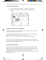
Page 41: ...lling and Removing the Battery Pack To Remove the Battery Pack 1 Place the notebook bottom side up on a flat and secured surface 2 Push the latch and pull the battery s hard case away from the noteboo...

Page 42: ...he battery charge indicator becomes green Note If the system runs at heavy loading or in a high temperature environment the battery may not be fully charged You need to continue to charge it with the...

Page 43: ...space reserved for this function The life expectancy of the battery is approximately 300 recharges See the notices section in the beginning of the user manual on how to care for the battery pack Note...

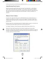
Page 44: ...to provide the user with an easy to use interface The Power Schemes tab can be found in the Power Options Properties panel that is accessible via the control panel window Schemes are easy to understa...

Page 45: ...n column and in the Running On Batteries column Lower time out values will save more battery power Note Also consult the Windows user guide for more information on how to use Windows power management...

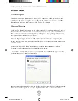
Page 46: ...o power or very little power is drawn from the battery module under this mode However depending on how much RAM has been installed in your computer the amount of time the system requires to restore al...

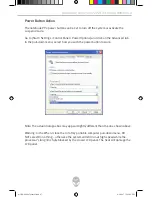
Page 47: ...l down menu select how you wish the power button to work Note The actual dialogue box may appear slightly different than the one shown above Warning In the When I close the lid of my portable computer...

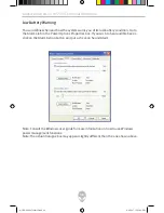
Page 48: ...he Power Options Properties box If you wish to hear audible beeps click on the Alarm Action button and put a check on Sound Alarm Note Consult the Windows user guide for more information on how to use...

Page 49: ...right hand corner of the task bar If you do not see a battery or AC in icon go to the Power Options Properties box and click on the Advanced tab Check off Always show icon on the task bar Select Max B...

Page 50: ...processor power usage but other system peripherals as well Go to Start Control Panel and click on the battery options under the mobile section High performance mode puts the processor into maximum pe...

Page 51: ...Note Also consult the Windows user guide for more information on how to use Windows power management functions Note The actual dialogue box may appear slightly different than the one shown above m555...

Page 52: ...all system state and contents are saved to the hard disk drive after a period of inactivity defined by the user No power or very little power is drawn from the battery module under this mode However...

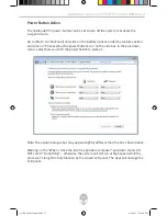
Page 53: ...ns do on the side bar In the pull down menu select how you wish the power button to work as Note The actual dialogue box may appear slightly different than the one shown above Warning In the When I cl...

Page 54: ...an in the Power Options Properties box Next click on Change advance power settings and go the the battery section and expand it to change the battery notifications and alarms Note Consult the Windows...

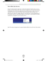
Page 55: ...icking on the Battery icon at the lower right hand corner of the task bar If you do not see a battery or AC in icon go to Power Options Properties box and click on the Advanced tab Check off Always sh...

Page 56: ...l Reference 56 CHAPTER FOUR UPGRADING YOUR COMPUTER In this chapter you will learn how to upgrade the DRAM and hard disk drive and how to install the optional wireless LAN mini PCI m5550 04 2007 techr...

Page 57: ...to make a backup copy of all your data before attempting this operation Warning A hard drive upgrade is a delicate process Please observe the following instructions carefully or have a qualified techn...

Page 58: ...urn OFF the computer Unhook the AC cord and all cables devices attached to the notebook Remove the battery 2 Place your hand on a large metal object momentarily to discharge any static electricity 3 L...

Page 59: ...Screw C s Note the green PC board of the hard disk drive is facing against the metal case 9 Re attach the HDD module to the HDD connector and re attach 1 Screw B 10 Put the HDD cover back and re atta...

Page 60: ...and runs on 2 5V The SO DIMM should be PC2 3200 or PC2 4200 compliant Warning A memory upgrade is a delicate process Please observe the following instructions carefully or have a qualified technician...

Page 61: ...evices attached to the notebook Remove the battery 2 Place your hand on a large metal object momentarily to discharge any static electricity Place the notebook on a flat surface and fully close the LC...

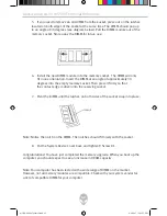
Page 62: ...ocket Then press it firmly so that the contact edge is driven into the receiving socket 7 Pivot the DIMM until the latches on both sides of the socket snap into place Note Notice the notch on the DIMM...

Page 63: ...lity of the mini PCI card Warning Installing a mini PCI card is a delicate process Please observe the following instructions carefully or have a qualified technician install it for you Damages due to...

Page 64: ...n the module with the socket on the connector and insert the card at an angle of approximately 30 degrees into the empty socket Then press it firmly so that the contact edge is driven into the receivi...

Page 65: ...socket 4 Replace the System Device Cover and 9 Screw D s Congratulations You have now completed the mini PCI card installation The next time the system boots to Windows the system will prompt for the...

Page 66: ...nware Area 51 m5550 Technical Reference 66 CHAPTER FIVE TROUBLESHOOTING In this chapter you will learn how to solve common hardware and software problems m5550 04 2007 techref indd 66 4 6 2007 12 29 5...

Page 67: ...holding any key Check for any incorrect or loose cable connections Make sure the latches on the connectors latch securely on to the receptor end Be sure you have not performed an incorrect setting on...

Page 68: ...Go to Start Settings Control Panel and double click the Sounds and Audio Devices icon In the Audio page make sure that Realtek HD Audio is the default playback device Sound cannot be recorded Double...

Page 69: ...ive The hard drive is making abnormal whining noises You should back up your files as soon as possible Make sure the source of the noise is indeed from the hard drive and not the fan or other devices...

Page 70: ...erform a diskdefragmentation This operation may take a while Interrupt requests or problems with other hardware devices may have occupied the CPU and therefore slow down the system performance The fil...

Page 71: ...d onto the spindle The disk is damaged or not readable The disk cannot be ejected Normally it takes a few seconds to eject the disk If the disk cannot be ejected it may be mechanically jammed Straight...

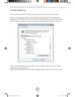
Page 72: ...modes The screen is difficult to read The display resolution should be set to at least 1024x768 for optimal viewing 1 Go to Start Settings Control Panel and double click the Display icon 2 Under the S...

Page 73: ...If you are connecting an external keyboard to the system the built in keyboard may not work Try restarting the system The characters on the screen repeat when I type You may be holding the keys down t...

Page 74: ...details Memory Problems The POST does not show an increased memory capacity when you have already installed additional memory Certain brands of memory module may not be compatible with your system You...

Page 75: ...to handle such problems Make sure the phone line which the computer is connected to is working Connection difficulties Be sure to disable Call Waiting on the phone line Be sure to have the correct co...

Page 76: ...pdate the device driver from the factory CD ROM disk or consult the Windows manual on how to solve the resource conflict problem Make sure the physical connections on both ends of the cable are good T...

Page 77: ...d should be even with the edge of the computer Remove and insert the PC card again Make sure there is no IRQ conflict with the card See Windows online help for solving IRQ conflicts Reboot the compute...

Page 78: ...ck to protect itself from thermal damage The program appears to have stopped or runs very slowly Press CTRL ALT DEL to see if an application is still responding Restart the computer This may be normal...

Page 79: ...y which reads Texas Instrument OHCI Compliant IEEE 394 Host Controllers If it does not exist Windows has not detected the host controller or the device driver has not been installed properly If there...

Page 80: ...Alienware Area 51 m5550 Technical Reference 80 APPENDIX A PRODUCT SPECIFICATIONS m5550 04 2007 techref indd 80 4 6 2007 12 29 53 PM...

Page 81: ...bit bus Two 200 pin DIMM sockets Max 2 GB Display 15 4 inch 1280x800 WXGA TFT display with 24 bit colors or 15 4 inch 1920x1200 WUXGA TFT display with 24 bit colors PCI Express bus architecture graph...

Page 82: ...Jam and auto negotiation for flow control Auto Negotiation and Parallel detection for automatic speed selection IEEE 802 3u High performance 32 bit PCI bus master architecture with integrated DMA con...

Page 83: ...ack One Firewire IEEE1394 host connector Three USB2 0 compliant connectors One standard network Ethernet connector RJ 45 One modem phone connector RJ11 One S video TV out output connector One DC in co...

Page 84: ...e Two Level Password Protections 32bit access Ultra DMA PIO5 Mode support Multi boot capability Compatible with Microsoft Windows XP MCE Home Edition Physical Specification 360 W x 269 D x 25 37 1 H m...

Page 85: ...Alienware Area 51 m5550 Technical Reference 85 APPENDIX B AGENCY REGULATORY NOTICES m5550 04 2007 techref indd 85 4 6 2007 12 29 54 PM...

Page 86: ...measures Reorient or relocate the receiving antenna Increase the separation between the equipment and the receiver Connect the equipment into an outlet on a circuit different from that to which the r...

Page 87: ...2001 EN50082 IEC801 2 IEC801 3 IEC801 4 Electro magnetic Immunity EN 300 328 2 EN 300 328 1 EN 301 489 1 EN 301 489 17 ETSI 300 328 ETSI 301 489 Electro magnetic Compatibility and Radio Spectrum Matt...

Page 88: ...A Certified or C UL Listed The minimum specifications for the flexible cord are 1 No 18 AWG 2 Type SJ and 3 3 conductor The cord set must have a rated current capacity of at least 10 A The attachment...

Page 89: ...ermany SASO Saudi Arabia The flexible cord must be of a HAR harmonized type HO5VV F 3 conductor cord with a minimum conductor size of 0 03 square inches The minimum specification for the flexible cord...

Page 90: ...it contacts the eye flush the eye with water for 15 minutes and seek medical attention Do not charge the battery pack if the ambient temperature exceeds 45o C 113o F To obtain a replacement battery c...

Page 91: ...rmful to the eyes The use of optical instruments such as magnifying lenses with this product increase the potential hazard to your eyes For your safety have this equipment serviced only by an authoriz...

Page 92: ...e computer This allows you to access and transmit data in the local area network Connecting to the Network Use Unshielded Twisted Pair UTP Ethernet cable only 1 Insert one end of the UTP cable into th...

Reviews: