background image

Alienware Area-51 m9750 Technical Reference

7

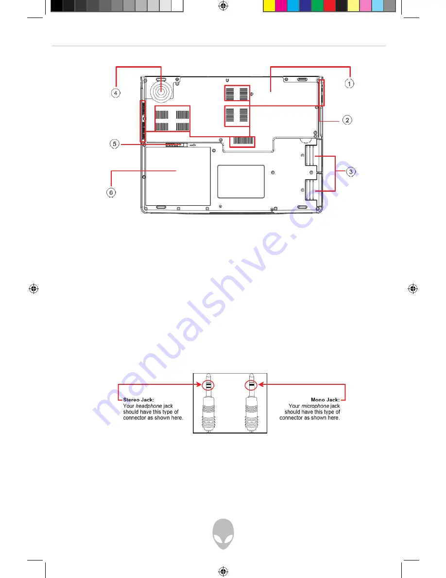
Bottom View


1. Compartment Door 


4. Woofer 

2. Ventilation Holes 


5. Battery Latch 

3. Two HDD Doors 


6. Battery Pack

Two Types of Audio Jack

us-area51-9750-techref-05-2007.i7   7

5/8/2007   4:07:03 PM

Summary of Contents for Area-51 m9750

Page 1: ...Use of this copyright protect technology must be authorized by Macrovision and is intended for home and other limited viewing uses only unless otherwise authorized by Macrovision Reverse engineering...

Page 2: ...S 12 OPERATING TEMPERATURE 13 THE FN KEY 14 CHAPTER 2 BATTERY 16 BATTERY PACK 16 RECHARGING THE BATTERY PACK 16 QUESTIONS AND ANSWERS 16 BATTERY MAINTENANCE 17 POWER CONSUMPTION 18 REDUCING POWER CONS...

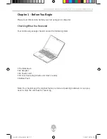
Page 3: ...t You Received Your notebook package should contain the following items The Notebook AC Adapter AC Power Cord CD Disc Including Drivers and User s Guide Battery Pack Note You should keep the original...

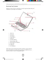
Page 4: ...LCD Latch LCD Screen Power Button Keyboard Two Click Buttons Seven System LEDs Nine Finger Touch Buttons Touch Pad ODD Drive Two Speakers 1 2 3 4 5 6 7 8 9 10 11 Note Press this key combination Fn F4...

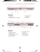
Page 5: ...R Infrared Receiver Underneath 6 ODD Drive Rear View 1 VGA Port 7 S Video In Connector 2 S Video Out Connector 8 DC In Jack 3 Ventilation Holes 9 USB Connector 4 RJ11 Fax Modem Connector 10 DVI Connec...

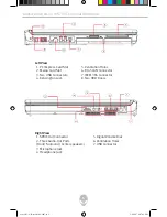
Page 6: ...AN Connector 3 Two USB Connectors 7 IEEE1394 Connector 4 Kensington Lock 8 Two HDD Doors Right View 1 SPDIF Out Connector 5 Digital Volume Dial 2 Three Audio Out Ports 6 Ventilation Holes Front Surrou...

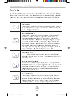
Page 7: ...51 m9750 Technical Reference Bottom View 1 Compartment Door 4 Woofer 2 Ventilation Holes 5 Battery Latch 3 Two HDD Doors 6 Battery Pack Two Types of Audio Jack us area51 9750 techref 05 2007 i7 7 5 8...

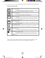
Page 8: ...e and The battery pack fails to be recharged Purple blinking once per second The system is in standby mode and The battery pack fails to be recharged Amber blinking once per 3 seconds The battery pack...

Page 9: ...on The HDD ODD LED The LED will be lit when the system is accessing the hard disk drive and or optical drive The AC Adapter LED The LED will be lit when the system is connected to an AC adapter The Wi...

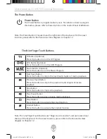
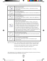
Page 10: ...n Optional Press this button to run the Music Program Next Track Button Press this button to skip to the next track chapter of media playback Previous Track Button Press this button to skip to the pre...

Page 11: ...unction Key Controller program as supplied in the system driver CD Without installing this program you will not be able to activate these functions through these three buttons unless you have entered...

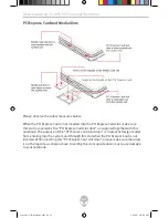
Page 12: ...lot door as supplied together with this notebook The purpose of this PCI Express Card slot door is to prevent foreign matter from entering into the system unit through this slot when the PCI Express C...

Page 13: ...se of this media slot door is to prevent foreign matter from entering into the system unit through this slot when no card is inserted When inserting this media slot door please make sure the arrow is...

Page 14: ...mbination Fn F2 is to provide you with a quick way to turn off the power of Wireless LAN when entering venues like airplanes airports and hospitals where the usage of Wireless LAN is prohibited or not...

Page 15: ...Fn F9 is to provide you with a quick way to turn off the power of Bluetooth when entering venues like airplanes airports and hospitals where the usage of Bluetooth is prohibited or not advisable Alien...

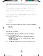
Page 16: ...s For details on the System LEDs please refer to Chapter 1 3 When the notebook is OFF a depleted Li Ion battery will take three hours to recharge Questions and Answers Q I can feel a mild heat next to...

Page 17: ...will become too low and needs to be Pre Charged to bring the battery voltage level high enough before it automatically for Li Ion only resumes its normal Fast Charge Pre Charge may take 30 minutes Fas...

Page 18: ...em in detail The Power Options in Windows XP are further divided into the categories below Power Schemes Alarms Power Meter Advanced Hibernate Windows Vista s Power Options include three preferred pow...

Page 19: ...power is on make sure this battery pack is not the only electrical source to the system unit Follow the steps below to remove the battery pack Have the system properly shutdown Flip the system upside...

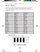
Page 20: ...es all the possible ways system memory can be configured Total Memory Socket 1 Socket 2 256MB 0MB 256MB 256MB 256MB 0MB 512MB 0MB 512MB 512MB 256MB 256MB 512MB 512MB 0MB 768MB 256MB 512MB 768MB 512MB...

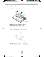
Page 21: ...tdown Flip the system upside down as shown Remove the battery pack as shown in Chapter 2 Remove the four screws as shown by 1 Remove the compartment door as shown by 2 Press the spring locks sideways...

Page 22: ...ss the spring locks sideways as shown by 1 The second memory module will pop up as shown by 2 Remove the second memory module as shown by 3 To insert the memory modules reverse the steps above us area...

Page 23: ...e major scenarios One Windows bootable HDD drive You are at your liberty to use either one of the two sockets But the primary socket is your preferred choice for the bootable HDD drive One Windows boo...

Page 24: ...stem is properly shutdown Flip the system upside down as shown Remove the battery pack as shown in Chapter 2 Remove the two screws as shown by 1 Remove the two HDD drives as shown by 2 Remove the four...

Page 25: ...ating DO NOT COVER THE VENTILATION OPENINGS CAUTION Verify the voltage of the power source before connecting the unit to any power outlet WARNING DO NOT step on or place anything over the power cord C...

Page 26: ...There is a risk of explosion and injury if the battery is incorrectly replaced or handled Do not attempt to recharge disassemble immerse in water or dispose of it in fire Replacement should be done th...

Page 27: ...o your notebook CAUTION The AC Adapter can accept a line voltage ranging from 100V to 240V and is compatible with most international power sources If you are unsure whether your power source is compat...

Page 28: ...eption which can be determined by turning the equipment off and on the user is encouraged to try to correct the interference by one or more of the following measures Reorient or relocate the receiving...

Page 29: ...tions should be observed Do not touch or move the antenna while the unit is transmitting or receiving Do not hold any component containing the radio such that the antenna is very close or touching any...

Page 30: ...du Reglement sur le materiel brouilleur du Canada Canada Radio Frequency Interference Requirements This Class B digital apparatus complies with Canadian ICES 003 Issue 2 and RSS 210 Issue 4 Dec 2000...

Page 31: ...issions for Radio Equipment EN60950 Safety ETSI300328 2 Technical Requirements for Radio Equipment CE Caution Due to the fact that the frequencies used by 802 11b 802 11g wireless LAN devices may not...

Page 32: ...harente 57 Moselle 84 Vaucluse 19 Corr ze 58 Ni vre 86 Vienne 2A Corse Sud 59 Nord 88 Vosges 2B Haute Corse 60 Oise 89 Yonne 21 C te d Or 61 Orne 90 Territoire de Belfort 24 Dordogne 63 Puy du D me 91...

Page 33: ...e above are as follows See the ART website at www art telecom fr for information on the French overseas territories Frequency Ranges MHz Indoors Outdoors 2400 2446 5 10 mW Not permitted 2446 5 2483 5...

Page 34: ...ur right to file a compliant with the FCC Your telephone company may make changes in its facilities equipment operations or procedures that could affect proper operation of your equipment If they do y...

Page 35: ...ate the approval There is no guarantee of correct working in all circumstances Any difficulties should be referred to your supplier Some network operators require that intended users of their network...

Reviews: