background image

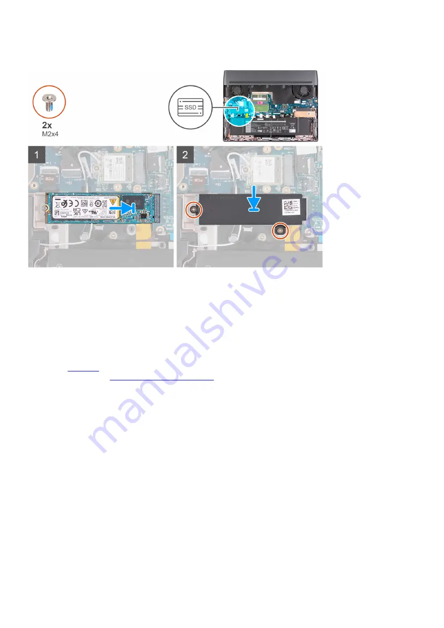
The following image(s) indicate the location of the M.2 2280 solid-state drive in slot one and provides a visual representation of the

installation procedure.

Steps
1. 
Align the notch on the M.2 2280 solid-state drive with the tab on the M.2 card slot on the system board.
2. Slide the M.2 2280 solid-state drive into the M.2 card slot on the system board.
3. Slide the tab on the M.2 2280 thermal shield into the M.2 card slot and align the screw holes on the thermal shield to the screw

holes on the palm-rest and keyboard assembly.

4. Replace the two screws (M2x4) that secure the M.2 2280 thermal shield to the palm-rest and keyboard assembly.

Next steps
1. 
Install the 

base cover

.

2. Follow the procedure in 

After working inside your computer

.

Procedure to move the screw mount in SSD slot one

About this task
This computer supports two solid-state drive form factors in SSD slot one:

M.2 2230

M.2 2280

If you are replacing the current solid-state drive in SSD slot one, with another solid-state drive that is of a different form factor, see

the following procedure to move the location of the screw mount in SSD slot one.

Steps
1. 
Slide to remove the screw mount from the palm-rest and keyboard assembly.
2. Slide the screw mount into the other screw mount slot on the palm-rest and keyboard assembly.

21

Summary of Contents for m17 R5 AMD

Page 1: ...Alienware m17 R5 AMD Service Manual Regulatory Model P50E Regulatory Type P50E001 P50E002 P50E003 March 2022 Rev A00 ...

Page 2: ...ential damage to hardware or loss of data and tells you how to avoid the problem WARNING A WARNING indicates a potential for property damage personal injury or death 2022 Dell Inc or its subsidiaries All rights reserved Dell EMC and other trademarks are trademarks of Dell Inc or its subsidiaries Other trademarks may be trademarks of their respective owners ...

Page 3: ... 2 2280 solid state drive in slot one 20 Procedure to move the screw mount in SSD slot one 21 Removing the M 2 2230 solid state drive in slot two 22 Installing the M 2 2230 solid state drive in slot two 23 Removing the M 2 2280 solid state drive in slot two 24 Installing the M 2 2280 solid state drive in slot two 25 Procedure to move the screw mount in SSD slot two 26 Memory module 27 Removing the...

Page 4: ...hernet and audio board 60 USB board 61 Removing the USB board 61 Installing the USB board 62 Power button 63 Removing the power button 63 Installing the power button 64 Palm rest and keyboard assembly 65 Removing the palm rest and keyboard assembly 65 Installing the palm rest and keyboard assembly 66 Chapter 3 Drivers and downloads 68 Chapter 4 System setup 69 Entering BIOS setup program 69 Naviga...

Page 5: ...ystem diagnostic lights 77 SupportAssist diagnostics 78 Built in self test BIST 79 M BIST 79 LCD Built in Self Test BIST 79 Recovering the operating system 80 WiFi power cycle 80 Drain residual flea power perform hard reset 80 Backup media and recovery options 81 Chapter 6 Getting help and contacting Alienware 82 5 ...

Page 6: ...liance WARNING Disconnect your computer from all power sources before opening the computer cover or panels After you finish working inside the computer replace all covers panels and screws before connecting your computer to an electrical outlet CAUTION To avoid damaging the computer ensure that the work surface is flat dry and clean CAUTION To avoid damaging the components and cards handle them by...

Page 7: ...ection Touching the chassis before handling parts does not ensure adequate ESD protection on parts with increased sensitivity to ESD damage Handle all static sensitive components in a static safe area If possible use anti static floor pads and workbench pads When unpacking a static sensitive component from its shipping carton do not remove the component from the anti static packing material until ...

Page 8: ...se only the inside of the bag is shielded Always place parts in your hand on the ESD mat in the system or inside an anti static bag Transporting Sensitive Components When transporting ESD sensitive components such as replacement parts or parts to be returned to Dell it is critical to place these parts in anti static bags for safe transport ESD protection summary It is recommended that all field se...

Page 9: ...4 Connect your computer and all attached devices to their electrical outlets 5 Turn on your computer 9 ...

Page 10: ...e correct number of screws and correct screw type is restored when the component is replaced NOTE Some computers have magnetic surfaces Ensure that the screws are not left attached to such surfaces when replacing a component NOTE Screw color may vary with the configuration ordered Table 1 Screw list Component Screw type Quantity Screw image Base cover M2 5x14 captive screw 2 Base cover M2 5x6 capt...

Page 11: ...Touchpad bracket M2x2 2 Touchpad M2x2 2 Keyboard controller board M2x2 1 Type C bracket M2x4 2 System board M2x4 13 Fan and heat sink assembly M2x4 6 Ethernet and audio board M2x4 2 USB board M2x4 2 Power button M2x2 3 Major components of Alienware m17 R5 AMD The following image shows the major components of Alienware m17 R5 AMD 11 ...

Page 12: ...acket 12 Left speaker 13 Keyboard controller board 14 Ethernet and audio board 15 Type C bracket 16 Power button 17 Power button bracket 18 Power adapter port bracket 19 Power adapter port 20 Battery 21 M 2 2280 solid state drive slot 1 22 M 2 2280 solid state drive thermal shield slot 1 23 M 2 2280 solid state drive slot 2 24 M 2 2280 solid state drive thermal shield slot 2 25 Rear I O cover 12 ...

Page 13: ...ranty coverages purchased by the customer Contact your Dell sales representative for purchase options Base cover Removing the base cover Prerequisites 1 Follow the procedure in Before working inside your computer About this task The following image s indicate the location of the base cover and provides a visual representation of the removal procedure 13 ...

Page 14: ...14 ...

Page 15: ...e cover 5 Slide and lift the base cover off the palm rest and keyboard assembly 6 Peel the tape that secures the battery cable to the battery 7 Disconnect the battery cable from the system board 8 Turn over the computer and open the display 9 Press and hold the power button for 20 seconds to ground the computer and drain the flea power Installing the base cover Prerequisites If you are replacing a...

Page 16: ...16 ...

Page 17: ...yboard assembly 4 Tighten the two captive screws M2 5x6 on the base cover that secure the base cover to the palm rest and keyboard assembly 5 Tighten the two captive screws M2 5x14 on the base cover that secure the base cover to the palm rest and keyboard assembly 6 Replace the four screws M2 5x5 that secure the base cover to the palm rest and keyboard assembly Next steps 1 Follow the procedure in...

Page 18: ...s procedure is applicable only to computers shipped with NVIDIA GeForce RTX 3050 Ti graphics card The following image s indicate the location of the M 2 2230 solid state drive in slot one and provides a visual representation of the removal procedure Steps 1 Remove the two screws M2x4 that secure the M 2 2230 thermal shield to the palm rest and keyboard assembly 2 Slide and remove the M 2 2230 ther...

Page 19: ...solid state drive with the tab on the M 2 card slot on the system board 2 Slide the M 2 2230 solid state drive into the M 2 card slot on the system board 3 Align and place the solid state drive thermal shield on the solid state drive 4 Align the screw hole on the solid state drive thermal shield with the screw hole on the solid state drive and palm rest and keyboard assembly 5 Replace the two scre...

Page 20: ... Steps 1 Remove the two screws M2x4 that secure the M 2 2280 thermal shield to the palm rest and keyboard assembly 2 Lift the M 2 2280 thermal shield off the solid state drive 3 Slide and remove the M 2 2280 solid state drive from the solid state drive slot Installing the M 2 2280 solid state drive in slot one Prerequisites If you are replacing a component remove the existing component before perf...

Page 21: ...wo screws M2x4 that secure the M 2 2280 thermal shield to the palm rest and keyboard assembly Next steps 1 Install the base cover 2 Follow the procedure in After working inside your computer Procedure to move the screw mount in SSD slot one About this task This computer supports two solid state drive form factors in SSD slot one M 2 2230 M 2 2280 If you are replacing the current solid state drive ...

Page 22: ...n Before working inside your computer 2 Remove the base cover About this task NOTE This procedure is applicable only to computers shipped with an M 2 2230 solid state drive installed in M 2 slot two SSD2 NOTE The M 2 card installed on M 2 slot two SSD2 will depend on the configuration ordered Supported card configurations M 2 2230 solid state drive M 2 2280 solid state drive The following image s ...

Page 23: ...t two Prerequisites If you are replacing a component remove the existing component before performing the installation process About this task NOTE This procedure is applicable if you are installing a M 2 2230 solid state drive into M 2 slot two SSD2 NOTE Supported card configurations on M 2 slot two SSD2 M 2 2230 solid state drive M 2 2280 solid state drive The following image s indicate the locat...

Page 24: ...mbly Next steps 1 Install the base cover 2 Follow the procedure in After working inside your computer Removing the M 2 2280 solid state drive in slot two Prerequisites 1 Follow the procedure in Before working inside your computer 2 Remove the base cover About this task NOTE This procedure is applicable only to computers shipped with an M 2 2280 solid state drive installed in M 2 slot two SSD2 NOTE...

Page 25: ...Prerequisites If you are replacing a component remove the existing component before performing the installation process About this task NOTE This procedure is applicable if you are installing a M 2 2280 solid state drive into M 2 slot two SSD2 NOTE Supported card configurations on M 2 slot two SSD2 M 2 2230 solid state drive M 2 2280 solid state drive The following image s indicate the location of...

Page 26: ...board assembly Next steps 1 Install the base cover 2 Follow the procedure in After working inside your computer Procedure to move the screw mount in SSD slot two About this task This computer supports two solid state drive form factors in SSD slot two M 2 2230 M 2 2280 If you are replacing the current solid state drive in SSD slot two with another solid state drive that is of a different form fact...

Page 27: ...he M 2 2280 solid state drive in SSD slot two Memory module Removing the memory module Prerequisites 1 Follow the procedure in Before working inside your computer 2 Remove the base cover About this task NOTE This computer may have up to two memory modules installed The following image s indicate the location of the memory module and provides a visual representation of the removal procedure 27 ...

Page 28: ...the thermal pad is separated from the system board in the process of service procedures re adhere the thermal pad to the memory compartment on the system board before re installing the memory into the system NOTE Note the slot and the orientation of the memory module in order to replace it in the correct slot NOTE If the memory module is difficult to remove gently ease the memory module back and f...

Page 29: ...teps to install any other memory module into your computer NOTE The securing clips return to a locked position If you do not hear the click remove the memory module and reinstall it Next steps 1 Install the base cover 2 Follow the procedure in After working inside your computer Wireless card Removing the wireless card Prerequisites 1 Follow the procedure in Before working inside your computer 2 Re...

Page 30: ...tenna cables from the wireless card 4 Slide and remove the wireless card at an angle from the wireless card slot Installing the wireless card Prerequisites If you are replacing a component remove the existing component before performing the installation process About this task The following image s indicate the location of the wireless card and provides a visual representation of the installation ...

Page 31: ... and place the wireless card bracket on the wireless card 3 Align the notch on the wireless card with the tab on the wireless card slot and insert the wireless card at an angle into the wireless card slot 4 Align the screw hole on the wireless card bracket with the screw hole on the wireless card and palm rest and keyboard assembly 5 Replace the screw M2x4 that secures the wireless card bracket to...

Page 32: ...emove the two screws M2 5x5 that secure the rear I O cover to the palm rest and keyboard assembly 3 Remove the three screws M2x3 that secure the rear I O cover to the palm rest and keyboard assembly NOTE To prevent damaging your computer ensure that the Tron light cable has been disconnected from the system board before removing the rear I O cover 4 Firmly grasp the sides of your computer with bot...

Page 33: ...f the installation procedure Steps 1 With the correct orientation slide the rear I O cover into the palm rest and keyboard assembly and snap it into place NOTE To avoiding damaging your computer ensure the Tron light cable is not pinched before snapping the rear I O cover into place 2 Replace the three screws M2x3 that secure the rear I O cover to the palm rest and keyboard assembly 3 Replace the ...

Page 34: ...ct Dell technical support for assistance See www dell com contactdell Always purchase genuine batteries from www dell com or authorized Dell partners and resellers Swollen batteries should not be used and should be replaced and disposed properly For guidelines on how to handle and replace swollen Lithium ion batteries see Handling swollen Lithium ion batteries Removing the battery Prerequisites 1 ...

Page 35: ...hree screws M2x3 that secure the battery to the palm rest and keyboard assembly 4 Lift the battery off the palm rest and keyboard assembly Installing the battery Prerequisites If you are replacing a component remove the existing component before performing the installation process About this task The following image s indicate the location of the battery and provides a visual representation of the...

Page 36: ...ery cable to the battery Next steps 1 Install the base cover 2 Follow the procedure in After working inside your computer Battery cable Removing the battery cable Prerequisites 1 Follow the procedure in Before working inside your computer 2 Remove the base cover 3 Remove the battery About this task NOTE If the battery is disconnected from system board for service then there is a delay during boot ...

Page 37: ...e battery cable from the routing guides on the battery Installing the battery cable Prerequisites If you are replacing a component remove the existing component before performing the installation process About this task The following image s indicate the location of the battery cable and provides a visual representation of the installation procedure 37 ...

Page 38: ...ry over Next steps 1 Install the battery 2 Install the base cover 3 Follow the procedure in After working inside your computer Speakers Removing the speakers Prerequisites 1 Follow the procedure in Before working inside your computer 2 Remove the base cover About this task The following image s indicate the location of the speakers and provides a visual representation of the removal procedure 38 ...

Page 39: ...and left speaker along with its cable off the palm rest and keyboard assembly Installing the speakers Prerequisites If you are replacing a component remove the existing component before performing the installation process About this task The following image s indicate the location of the speakers and provides a visual representation of the installation procedure 39 ...

Page 40: ...keyboard assembly 3 Connect the speaker cable to the system board Next steps 1 Install the base cover 2 Follow the procedure in After working inside your computer Power adapter port Removing the power adapter port Prerequisites 1 Follow the procedure in Before working inside your computer 2 Remove the base cover 3 Remove the rear I O cover About this task The following image s indicate the locatio...

Page 41: ... the power adapter port cable from the system board 7 Peel the power adapter port cable from the system board 8 Remove the two screws M2x4 that secure the power adapter port bracket to the palm rest and keyboard assembly 9 Lift the power adapter port bracket off the palm rest and keyboard assembly Installing the power adapter port Prerequisites If you are replacing a component remove the existing ...

Page 42: ...power adapter port bracket to the palm rest and keyboard assembly 7 Route the display cable through the slot on the palm rest and keyboard assembly 8 Connect the Alien head LED cable to the system board 9 Adhere the display cable to the system board 10 Connect the display cable to the system board and close the latch to secure the cable 11 Adhere the tape that secures the display cable connector l...

Page 43: ...ad 4 Lift the keyboard controller board cable to access the touchpad screw 5 Remove the two screws M2x2 that secure the touchpad to the palm rest and keyboard assembly 6 Open the display and push the bottom side of the touchpad and remove the touchpad off the palm rest and keyboard assembly Installing the touchpad Prerequisites If you are replacing a component remove the existing component before ...

Page 44: ...ble to access the touchpad screw 5 Replace the two screws M2x2 that secure the touchpad to the palm rest and keyboard assembly 6 Connect the touchpad cable to the system board and close the latch to secure the cable 7 Align and place the touchpad bracket into slots on the palm rest and keyboard assembly 8 Replace the two screws M2x2 that secure the touchpad bracket to the palm rest and keyboard as...

Page 45: ...1 Follow the procedure in Before working inside your computer 2 Remove the base cover 3 Remove the rear I O cover About this task The following image s indicate the location of the display assembly and provides a visual representation of the removal procedure 45 ...

Page 46: ...splay cable from the slot on the palm rest and keyboard assembly 9 Remove the display cable and Alien head LED cable from the routing guides on the display assembly 10 Remove the camera cable from the routing guides on the display assembly 11 Remove the six screws M2 5x5 that secure the display assembly to the palm rest and keyboard assembly 12 Lift the display assembly off the palm rest and keybo...

Page 47: ...47 ...

Page 48: ...gh the slot on the palm rest and keyboard assembly 7 Connect the Alien head LED cable to the system board 8 Adhere the display cable to the system board 9 Connect the display cable to the system board and close the latch to secure the cable 10 Adhere the tape that secures the display cable connector latch to the system board 11 Adhere the tapes that secure the camera cable to the system board 12 R...

Page 49: ...t this task The following image s indicate the location of the keyboard controller board and provides a visual representation of the removal procedure Steps 1 Peel the Mylar on the keyboard controller board 2 Open the latch and disconnect the keyboard cable from the keyboard controller board 3 Open the latch and disconnect the keyboard backlight cable from the keyboard controller board 49 ...

Page 50: ...uisites If you are replacing a component remove the existing component before performing the installation process About this task The following image s indicate the location of the keyboard controller board and provides a visual representation of the installation procedure Steps 1 Connect the keyboard controller board cable to the keyboard controller board and close the latch to secure the cable 2...

Page 51: ...orking inside your computer 2 Remove the base cover 3 Remove the memory module 4 Remove the M 2 2230 solid state drive or M 2 2280 solid state drive in slot one whichever applicable 5 Remove the M 2 2230 solid state drive or M 2 2280 solid state drive in slot two whichever applicable 6 Remove the wireless card 7 Remove the rear I O cover 8 Remove the battery About this task The following image ind...

Page 52: ...2 card slot for solid state drive 1 13 Wireless card slot 14 Camera cable 15 Power button cable The following image s indicate the location of the system board and provides a visual representation of the removal procedure 52 ...

Page 53: ...tem board 12 Peel the power adapter port cable from the system board 13 Disconnect the right fan cable from the system board 14 Disconnect the speaker cable from the system board 15 Open the latch and disconnect the touchpad cable from the system board 16 Open the latch and disconnect the keyboard controller board cable from the system board 17 Disconnect the left fan cable from the system board 1...

Page 54: ...6 M 2 card slot for solid state drive 2 7 Battery cable 8 Touchpad connector 9 Keyboard controller board cable 10 Tron light cable 11 Left fan cable 12 M 2 card slot for solid state drive 1 13 Wireless card slot 14 Camera cable 15 Power button cable The following image s indicate the location of the system board and provides a visual representation of the installation procedure 54 ...

Page 55: ...55 ...

Page 56: ...system board 13 Connect the keyboard controller board cable to the system board and close the latch to secure the cable 14 Connect the touchpad cable to the system board and close the latch to secure the cable 15 Connect the speaker cable to the system board 16 Connect the right fan cable to the system board 17 Adhere the power adapter port cable to the system board 18 Connect the power adapter po...

Page 57: ...n slot two whichever applicable 6 Remove the wireless card 7 Remove the rear I O cover 8 Follow the procedure from step 1 to step 20 in Removing the system board NOTE The system board can be removed and installed along with the ethernet and audio board USB board and fan and heat sink assembly This simplifies the removal and installation procedure and avoids breaking the thermal bond between the sy...

Page 58: ...eat sink assembly to the system board 4 Lift the fan and heat sink assembly off the system board Installing the fan and heat sink assembly Prerequisites If you are replacing a component remove the existing component before performing the installation process About this task The following image s indicate the location of the fan and heat sink assembly and provides a visual representation of the ins...

Page 59: ...stalling the system board 2 Install the rear I O cover 3 Install the wireless card 4 Install the M 2 2230 solid state drive or M 2 2280 solid state drive in slot one whichever applicable 5 Install the M 2 2230 solid state drive or M 2 2280 solid state drive in slot two whichever applicable 6 Install the memory module 7 Install the base cover 8 Follow the procedure in After working inside your comp...

Page 60: ...thermal bond between the system board and heat sink About this task The following image s indicate the location of the ethernet and audio board and provides a visual representation of the removal procedure Steps 1 Turn the system board assembly over 2 Remove the two screws M2x4 that secure the ethernet and audio board to the system board assembly 3 Slide and remove the ethernet and audio board fro...

Page 61: ... one whichever applicable 5 Install the M 2 2230 solid state drive or M 2 2280 solid state drive in slot two whichever applicable 6 Install the memory module 7 Install the base cover 8 Follow the procedure in After working inside your computer USB board Removing the USB board Prerequisites 1 Follow the procedure in Before working inside your computer 2 Remove the base cover 3 Remove the memory mod...

Page 62: ...d provides a visual representation of the removal procedure Steps 1 Turn over the system board assembly 2 Remove the two screws M2x4 that secure the USB board to the system board assembly 3 Slide and remove the USB board from the system board assembly Installing the USB board Prerequisites If you are replacing a component remove the existing component before performing the installation process Abo...

Page 63: ... 5 Install the M 2 2230 solid state drive or M 2 2280 solid state drive in slot two whichever applicable 6 Install the memory module 7 Install the base cover 8 Follow the procedure in After working inside your computer Power button Removing the power button Prerequisites 1 Follow the procedure in Before working inside your computer 2 Remove the base cover 3 Remove the memory module 4 Remove the M ...

Page 64: ...ion of the removal procedure Steps 1 Remove the three screws M2x2 that secure the power button bracket to the palm rest and keyboard assembly 2 Lift the power button bracket off the power button 3 Lift the power button along with its cable off the palm rest and keyboard assembly Installing the power button Prerequisites If you are replacing a component remove the existing component before performi...

Page 65: ... applicable 5 Install the M 2 2230 solid state drive or M 2 2280 solid state drive in slot two whichever applicable 6 Install the memory module 7 Install the base cover 8 Follow the procedure in After working inside your computer Palm rest and keyboard assembly Removing the palm rest and keyboard assembly Prerequisites 1 Follow the procedure in Before working inside your computer 2 Remove the base...

Page 66: ...provides a visual representation of the removal procedure Steps After performing the pre requisites you are left with the palm rest and keyboard assembly NOTE Ensure that the solid state drive mounts on slot one and two are removed from the old palm rest and keyboard assembly before installing the new palm rest and keyboard assembly These solid state drive mounts will be installed into the new pal...

Page 67: ... in Installing the system board 3 Install the keyboard controller board 4 Install the display assembly 5 Install the touchpad 6 Install the power adapter port 7 Install the speakers 8 Install the battery 9 Install the rear I O cover 10 Install the wireless card 11 Install the M 2 2230 solid state drive or M 2 2280 solid state drive in slot one whichever applicable 12 Install the M 2 2230 solid sta...

Page 68: ...Drivers and downloads When troubleshooting downloading or installing drivers it is recommended that you read the Dell Knowledge Based article Drivers and Downloads FAQ 000123347 68 ...

Page 69: ... Moves to the previous field Down arrow Moves to the next field Enter Selects a value in the selected field if applicable or follow the link in the field Spacebar Expands or collapses a drop down list if applicable Tab Moves to the next focus area Esc Moves to the previous page until you view the main screen Pressing Esc in the main screen displays a message that prompts you to save any unsaved ch...

Page 70: ...on of the computer AC Adapter Type Displays the type of AC adapter System Memory Displays the size of memory installed Memory Speed Displays the speed of memory Keyboard Type Displays the type of keyboard installed on the computer Table 4 System setup options Advance menu Advanced Virtualization Enables or disables the Virtualization technology Default Enabled VT for Direct I O Enables or disables...

Page 71: ...ted custom charge start and stop Default Adaptive Advance Battery Charge Configuration Enable Advance Battery Charge Configuration from the beginning of the day to a specified work period Default Disabled Power Option Selects the power on option when the display is open Maintenance Data Wipe on next boot Enables or disables data wipe on the next boot Default Disabled BIOS Recovery from Hard Drive ...

Page 72: ...URITY MITIGATIONS TABLE WSSMT Enables or disables WSSMT Default Disabled Firmware TPM Enable or disable the firmware TPM Default Enabled PPI Bypass for Clear Command Allows you to control the TPM Physical Presence Interface PPI When enabled this setting will allow the OS to skip BIOS PPI user prompts when issuing the Clear command Changes to this setting take effect immediately Default Disabled En...

Page 73: ...e BIOS settings of your computer You can create a system password and a setup password to secure your computer CAUTION The password features provide a basic level of security for the data on your computer CAUTION Anyone can access the data stored on your computer if it is not locked and left unattended NOTE System and setup password feature is disabled Assigning a system setup password Prerequisit...

Page 74: ... existing system password and press Enter or Tab 4 Select Setup Password update or delete the existing setup password and press Enter or Tab NOTE If you change the System and or Setup password reenter the new password when prompted If you delete the System and or Setup password confirm the deletion when prompted 5 Press Esc and a message prompts you to save the changes 6 Press Y to save the change...

Page 75: ...ile to the bootable USB drive 4 Connect the bootable USB drive to the computer that needs the BIOS update 5 Restart the computer and press F12 6 Select the USB drive from the One Time Boot Menu 7 Type the BIOS setup program filename and press Enter The BIOS Update Utility appears 8 Follow the on screen instructions to complete the BIOS update Updating the BIOS from the F12 One Time boot menu Updat...

Page 76: ...a turn off state insert the USB drive where you copied the flash into a USB port of the computer 2 Turn on the computer and press F12 to access the One Time Boot Menu select BIOS Update using the mouse or arrow keys then press Enter The flash BIOS menu is displayed 3 Click Flash from file 4 Select external USB device 5 Select the file and double click the flash target file and then click Submit 6 ...

Page 77: ... a battery gets stuck in a device as a result of swelling do not try to free it as puncturing bending or crushing a battery can be dangerous Do not attempt to reassemble a damaged or swollen battery into a laptop Swollen batteries that are covered under warranty should be returned to Dell in an approved shipping container provided by Dell this is to comply with transportation regulations Swollen b...

Page 78: ...ailure 1 2 Unrecoverable SPI Flash Failure 2 1 Processor failure 2 2 System board BIOS or ROM Read Only Memory failure 2 3 No memory or RAM Random Access Memory detected 2 4 Memory or RAM Random Access Memory failure 2 5 Invalid memory installed 2 6 System board or chipset error 2 7 Display failure SBIOS message 2 8 Display failure EC detection of power rail failure 3 1 RTC power failure 3 2 PCI v...

Page 79: ... 1 TPM Detection Failure 2 4 Unrecoverable SPI Failure 4 If there is no failure with the system board the LCD will cycle through the solid color screens described in the LCD BIST section for 30 seconds and then power off LCD Built in Self Test BIST Dell laptops have a built in diagnostic tool that helps you determine if the screen abnormality you are experiencing is an inherent problem with the LC...

Page 80: ... SupportAssist OS Recovery WiFi power cycle About this task If your computer is unable to access the internet due to WiFi connectivity issues a WiFi power cycle procedure may be performed The following procedure provides the instructions on how to conduct a WiFi power cycle NOTE Some ISPs Internet Service Providers provide a modem router combo device Steps 1 Turn off your computer 2 Turn off the m...

Page 81: ...set see the knowledge base article 000130881 at www dell com support Backup media and recovery options It is recommended to create a recovery drive to troubleshoot and fix problems that may occur with Windows Dell proposes multiple options for recovering Windows operating system on your Dell PC For more information see Dell Windows Backup Media and Recovery Options 81 ...

Page 82: ...nware computer is uniquely identified by a Service Tag or Express Service Code To view relevant support resources for your Dell computer enter the Service Tag or Express Service Code at www dell com support For more information on how to find the Service Tag for your computer see Locate the Service Tag on your computer Videos providing step by step instructions to service your computer www youtube...

Reviews: