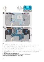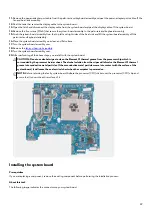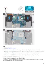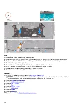
11. Slide the keyboard-controller board cable into the connector on the system board and close the latch to secure the cable.
12. Connect the speaker cable to the system board.
13. Connect the headset port cable to the system board and route it through the routing guides on the fan and heat-sink assembly.
14. Slide the I/O-board cable into the connector on the system board and close the latch to secure the cable.
15. Route the I/O-board cable through the routing guides on the fan and heat-sink assembly.
16. Adhere the tape that secures the I/O-board cable to the system board.
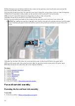
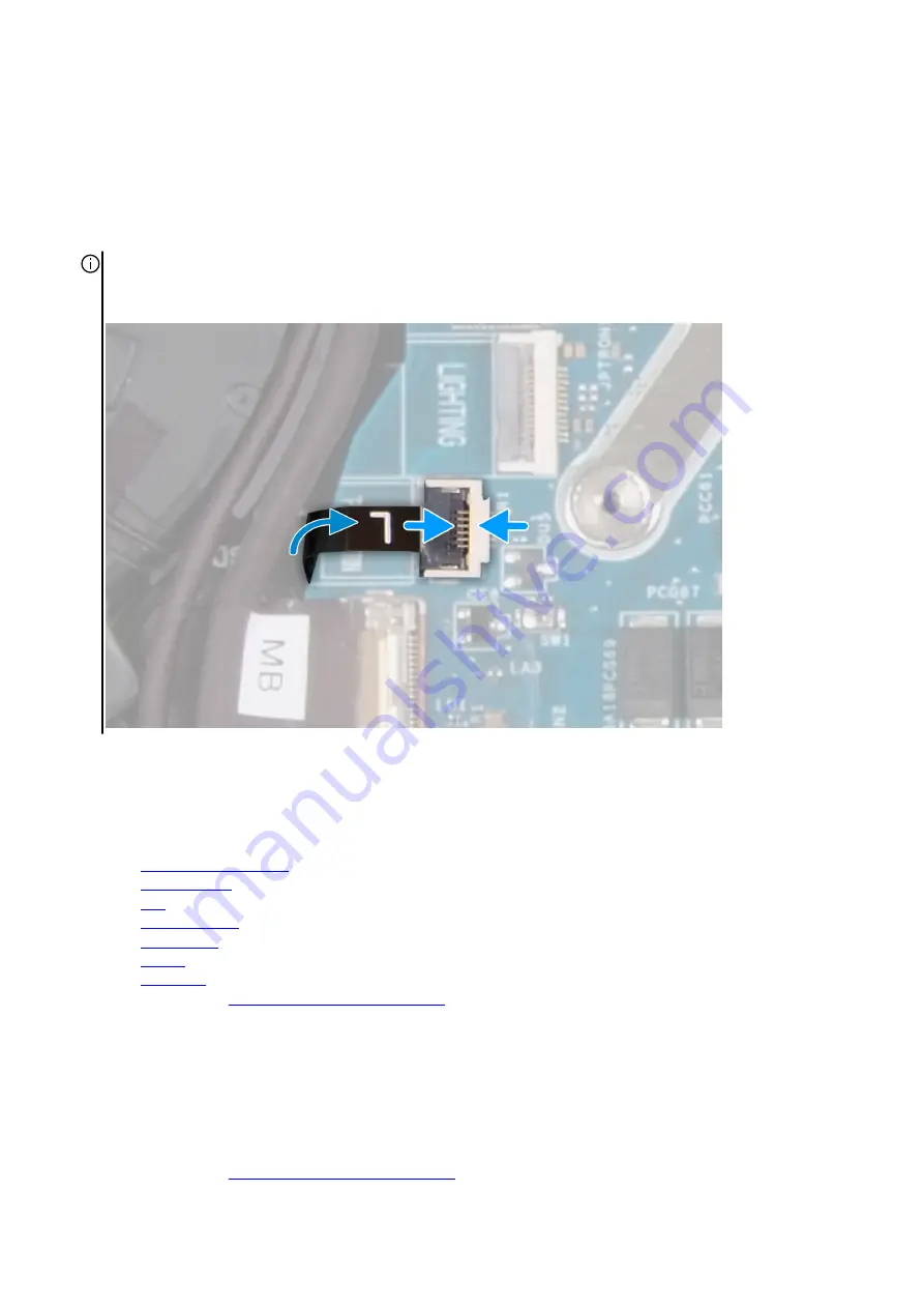
17. Slide the power-button board cable into the connector on the system board and close the latch to secure the cable.
NOTE: When installing the system-board assembly, ensure that the power-button board cable is placed on top of the system
board. Overlooking the power-button board cable connection to the system board will result in no-power failure after
service.
18. Adhere the Alien head LED cable to the system board and connect the Alien head LED cable to the system board.
19. Connect the camera cable to the system board and adhere the tape that secures the camera cable to the system board.
20.Adhere the headset-port cable to the palm-rest and keyboard assembly.
Next steps
1. Install the
.
2. Install the
.
3. Install the
4. Install the
5. Install the
.
6. Install the
7. Install the
.
8. Follow the procedure in
After working inside your computer
.
Fan and heat-sink assembly
Removing the fan and heat-sink assembly
Prerequisites
1. Follow the procedure in
Before working inside your computer
52

