background image

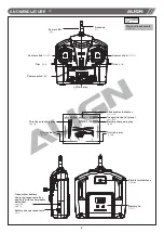
8.NOMENCLATURE 

» ±¾ ¦ ³ ¦ ¦ º

6

穘膘

LCD display

²´ ª

穘膘

¸ ¤¥·©¸

Do not disassemble

¸    ¤

FORBIDDEN

Power switch 

¹·¶Ã

Power LED

¹·«¥¿

Antenna

¤½

Control stick

Control stick

Trim 

°§·½Á

Trim 

°§·½Á

Battery lid

筿

»±¾¹¦¥¹¤

(

¨¥¥¹¹¦

)

Transmitter battery 
charging receptacle (for 
use only with rechargeable 
batteries)

battery charge receptacle

¹¦¥¹¤

Simulator interface

¼À¾³±¤

Stick modes Indicator

»±±¨¼¦«¥

Transmitter battery level

»±¾¹¶«¥

Battery charge display

¹¦¥¹«¥

Trim indicator

°§·½«¥

Throttle output display

ªª¿¥«¥

Trim indicator

°§·½«¥

Summary of Contents for Super Combo M424 Quadcopter V2

Page 1: ...6 1 2 7 5 9 10 11 11 12 17 19 19 3 PACKAGE ILLUSTRATION STANDARD EQUIPMENT QUADCOPTER NOMENCLATURE 3 STEPS FOR M424 V2 QUADCOPTER ASSEMBLY NOMENCLATURE TRANSMITTER BATTERY INSTALLATION CHARGING BATTE...

Page 2: ......

Page 3: ...roduct you are solely responsible for operating it in a manner that does not endanger yourself and others or result in damage to the product or the property of others M424 V2 We recommend that you obt...

Page 4: ...product is not used for long period of time please remove the batteries to prevent damaged caused by battery leaks Do not use batteries which exhibits symptoms of leaks Please dispose depleted batteri...

Page 5: ...LED LED LED LED LED 4 STANDARD EQUIPMENT x 4 Rotor blade x 4 AT100 AT100 AT100 Transmitter M424 V2 M424 V2 Quadcopter Li Polymer battery x 1 x 1 3 7V 530mAh 20C CH240 Li Po charger x 1 USB cable x 1 C...

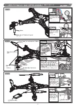
Page 6: ...lymer battery T1 5x4mm Socket button head self tapping screw Bearing 3x 6x2mm L aluminum rotational shaft 1 5x 3x37 6mm L Motor counter clockwise R Rotor blade normal rotation Fluorescent orange Socke...

Page 7: ...blue Aluminum rotational shaft The keyed flat spot in blade must match the keyed flat spot on aluminum shaft for proper installation of blade Press the LED s flat during installation the exposed part...

Page 8: ...l stick Control stick Trim Trim Battery lid Transmitter battery charging receptacle for use only with rechargeable batteries battery charge receptacle Simulator interface Stick modes Indicator Transmi...

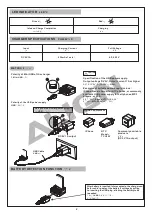
Page 9: ...o enable charge of Li Po batteries individually or concurrently The charger can be powered via two power source either connecting to the USB port on a computer or connecting to a third party USB power...

Page 10: ...y USB Polarity of Mini USB of the charger Mini USB CHARGER SPECIFICATIONS Input Full Voltage Charging Current 4 2 0 03V DC 5V 1A 530mA x1 sets CAUTION DC5V 1A Specification of the USB power supply Out...

Page 11: ...rging process can be done with transmitter powered off To check for charging status display the transmitter can be powered back on BATTERY USAGE AND CHARGE DURATION REFERENCE Battery type 3 7 V 530mAh...

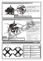
Page 12: ...ick mode has been set at the factory For switching to other modes please follow instructions below Note Amongst the 4 axis of the transmitter control sticks the axis that does not spring back to cente...

Page 13: ...1 has been set After transmitter is switched to mode 3 the mode will be retained every time when powered up as indicated by a long beep Using thumb and pointer fingers hold the aileron and rudder trim...

Page 14: ...ialize and the green LED on the receiver borad will be start flashing Push the throttle stick to the lowest position ON OFF 3 STEP 3 The green LED on receiver board will blink during radio initializat...

Page 15: ...mes steady after 4 seconds indicating successful radio binding If it continues to blink radio binding has failed and needs to be restarted Refer to P 12 Binding of radio transmitter and receiver CAUTI...

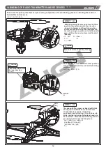
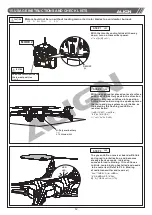
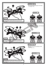
Page 16: ...not exceed half throttle always keep copter away from your face head 14 CAUTION During testing throttle stick need to be in the middle do not exceed 50 output position on the pitch curve CAUTION Duri...

Page 17: ...Front Elevator stick down quadcopter will tilt backward Front CAUTION CAUTION During testing throttle stick need to be in the middle do not exceed 50 output position on the pitch curve During testing...

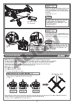
Page 18: ...seeable problems quadcopter Warning If left connected in the helicopter for long duration the battery may be damaged due to over discharge or even become fire hazards WARNING 5 STEP 5 Warning If the A...

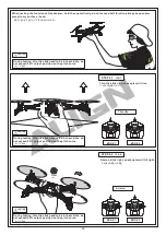
Page 19: ...ators to familiarize with all directional controls uadcopter Mode 1 1 2 3 17 Elevator Rudder Mode 2 Illustration Mode 1 Illustration Throttle Move right Move left Turn right Turn left Descent Ascent F...

Page 20: ...s in the opposite direction to fly back to its original position quadcopter Mode 1 CAUTION 2STEP AILERON AND ELEVATOR CONTROL PRACTICE 3STEP RUDDER CONTROL PRACTICING 1 Slowly raise the throttle stick...

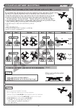
Page 21: ...trim Just before the lift off the body lean left right When leans right adjust the trim to left side When leans left adjust the trim to right side quadcopter Right Left Left Left Right Right Left Left...

Page 22: ...Me m o...

Page 23: ......

Page 24: ...m M424 V2 71mm 59mm AT 100 Specifications Equipment Length 240mm Height 50mm Propeller width 135mm Weight Without Battery 82g Flying Weight Approx 96g 2014 Jan 24 G00624A M424 V2 MADE IN TAIWAN 240mm...

Reviews: