background image

Align Trex Se Setup Guide


CP2 and CP3 can be increased if you are experienced or after you become 
comfortable with your heli. The transmitters default setting of 60% will give 
you about 12 degrees total cyclic travel, [ -, + 6 degrees]. At this high setting 
the mechanics are very near binding. In addition using that much cyclic may 
cause bogging. Shoot for 6 degrees total and then advance to around 9 
degrees total. 

The radio settings should now be very close to final with the exception of possible servo reversing, subtrims and gyro 
gain adjustments. 

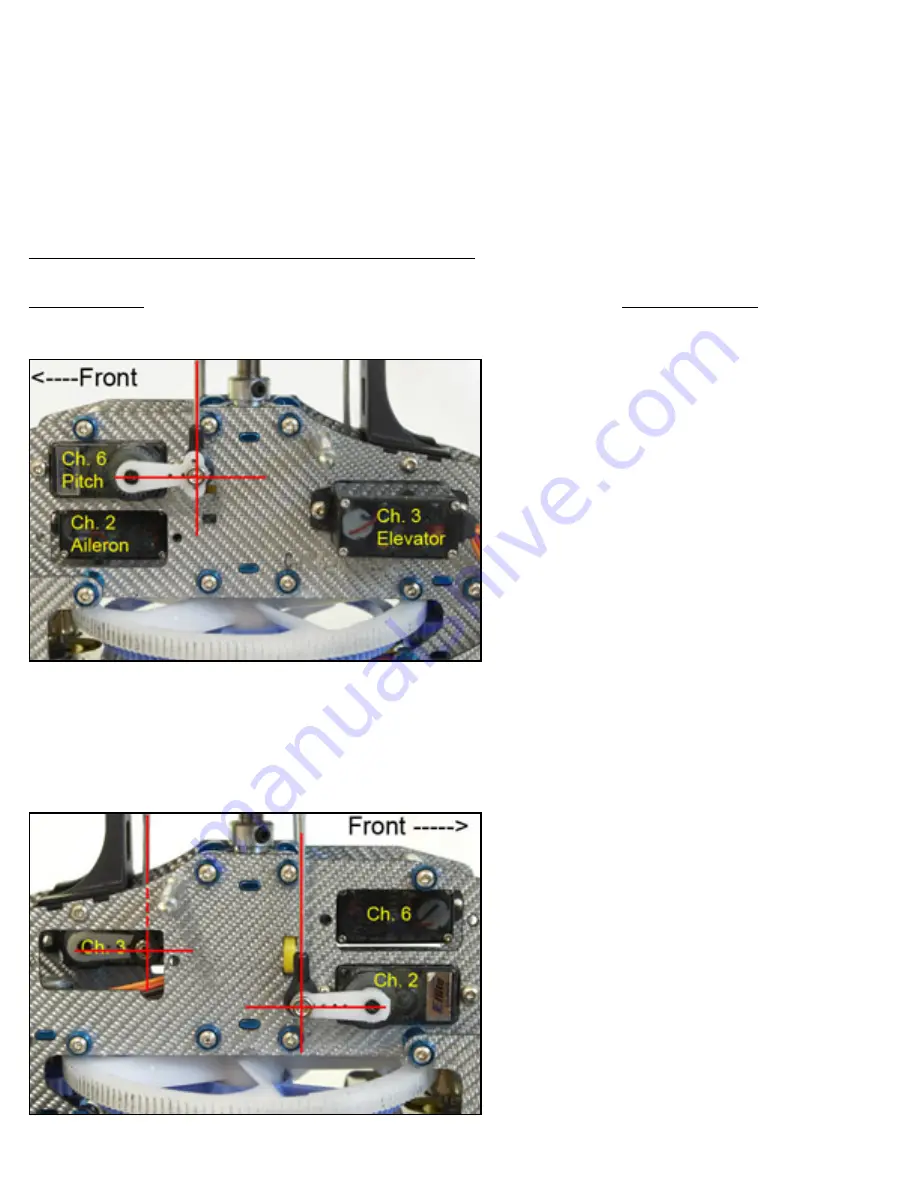
#2 Servo mounting, connections, direction and centering

Servo mounting may vary slightly but I found the following offers good alignment. Servo connections shown are for 
the DX6.

Figure A 

Note Ch. 6 servo is mounted from the inside and Ch. 3 is mounted from the outside of the left frame with the servo 
horn inside the frame halves.


Figure B 

http://www.digimemphoto.com/pdf/ (3 of 13)1/25/2006 7:09:05 PM

Summary of Contents for Trex SE

Page 1: ...so please see your manufacturers instructions for placing your radio into the correct helicopter mode in this case CCPM and other options such as servo reversing gyro gain etc Radio settings rates de...

Page 2: ...ect PLS P2S and PHS and set the following values using increase and decrease PLS 0 P2S 50 PHS 100 Press scroll to advance to the next Pitch Curve Menu Use the channel button select PLH P2H and PHH and...

Page 3: ...hen advance to around 9 degrees total The radio settings should now be very close to final with the exception of possible servo reversing subtrims and gyro gain adjustments 2 Servo mounting connection...

Page 4: ...ervo arm should move down and Channel 6 servo arm should move up If this is not the case you will need to reverse one or both of the servos depending on what reaction occurred Move the right stick cyc...

Page 5: ...t the linkage on the head assembly In order to correctly set up your new Trex you will need a pitch guage This tool is used to measure the pitch angle of the main rotor blades in relation to the flyba...

Page 6: ...the guage If all is well your flybar and top of guage will be parallel showing your pitch is at 0 Do the same for the other blade You should be right on if not very close You can make slight adjustme...

Page 7: ...tom of the main rotor housing figure J below The gap can be tighter than what is shown but they surfaces should not be butted together If you are unable to reach 10 degrees before the surfaces touch t...

Page 8: ...section and do this servo again You need to be in flight mode 1 With the servo centered horn on linkage connected loosen the servo mount bracket so it can be moved on the boom Position the servo so t...

Page 9: ...to push the tail away from you Watch the servo and not the direction it moves when you push the tail The servo horn should move towards the tail as in the diagram Pulling the tail towards you should r...

Page 10: ...full left rudder Listen for binding and check clearance figure P If you hear binding or see that there is zero clearance reduce the gyro travel limit on the gyro until you have some clearance Do the...

Page 11: ...ct with the main gear 6 Final Check Before attempting hover or flight there are several areas to check and are not limited to the following Binding Disconnect your motor leads for safety Give the heli...

Page 12: ...h Switch at 0 Normal operation Switch at 1 No motor operation Aileron D R Switch Switch at 0 Gyro Head Hold Mode ON should remain in this mode Switch at 1 Gyro Head Hold Mode OFF Elevator D R Switch F...

Page 13: ...erely steps shown to me by Bob to get SE straight and hopefully will do the same for others History 01 25 06 updated CP section of radio setup to better explain the function of CP2 CP3 and CP6 Added g...

Reviews: