25
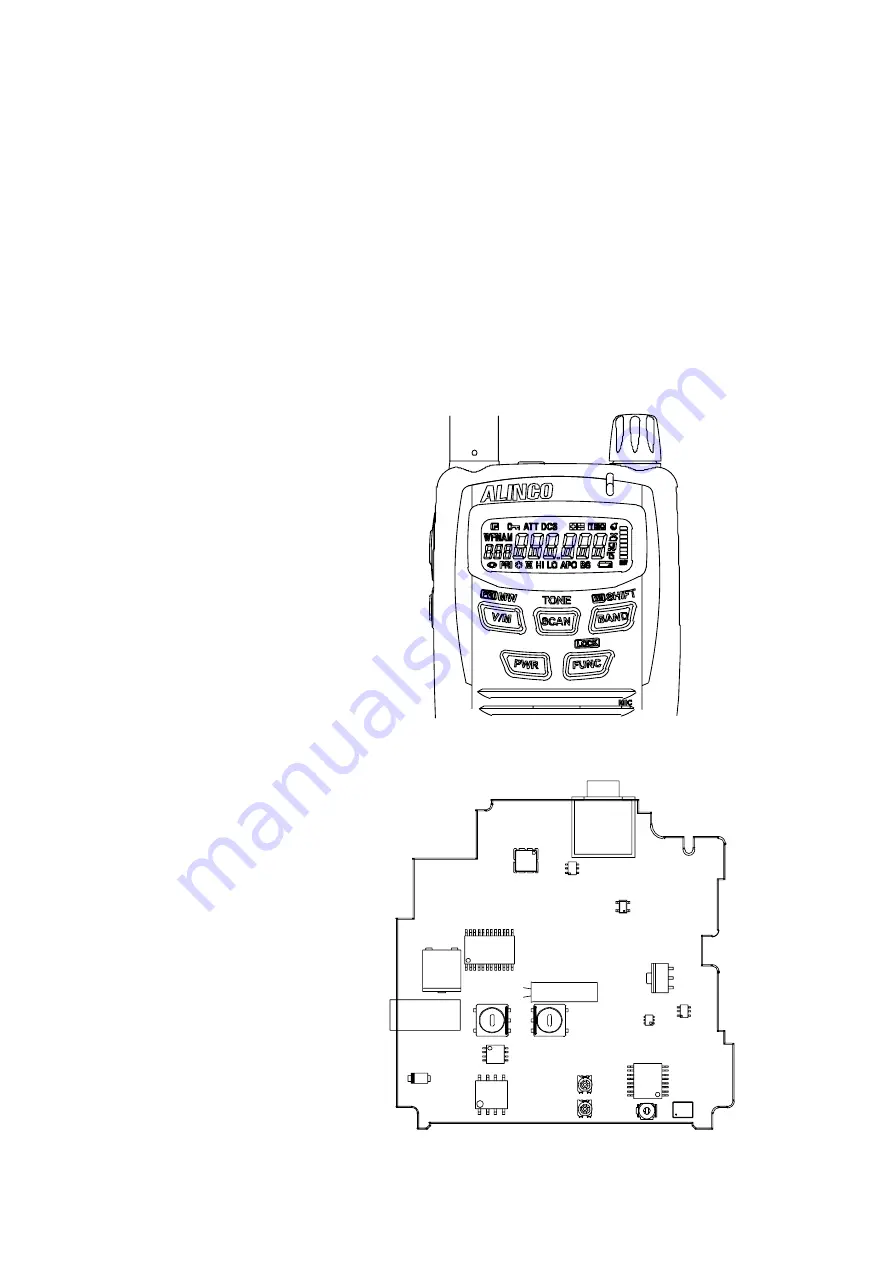
2) Entering and Releasing the Adjustment Mode
The DJ-C7 does not require a serviceperson to manipulate the components on the printed-circuit board, except
the trimmer when adjusting reference frequency and deviation. Most of the adjustments for the transceiver are
mode by using the keys on it while the unit is in the adjustment mode. Because the adjustment mode
temporarily uses the channels, frequency must be set on each channel before adjustments can be mode. For
instructions on how to program the channels, see the “DJ-C7 INSTRUCTION MANUAL” which came with the
product. In consideration of the radio environment, the frequency on each channel must be near the value
(+/-1MHz) listed in the table below. To enter the adjustment mode, set key lock and press [BAND], [V/M],
[SCAN], [V/M], [SCAN], [BAND], and [FUNC] key. “Freq” appears in LCD. When changing the adjustment
parameters, press the [SCAN] or [BAND] key.
To exit the adjustment mode, press the [MONI] key.
Adjustment Points
Front side
Rotary Encoder
RESW &
L40
VR1
TC1
VR2
L42
MIC/EAR JACK
Rear side
DC JACK
Summary of Contents for DJ - C7 T
Page 17: ...17 EXPLODED VIEW 1 Front View ...
Page 18: ...18 2 Rear View ...
Page 29: ...29 PC Board View MAIN Side A VCO CASE TS0174 ...
Page 30: ...30 MAIN Side B X2 No gap 1mm less than 1mm ...
Page 31: ...31 PC Board View KEY Side A MIC301 No gap ...
Page 32: ...32 KEY Side B ...
Page 33: ...33 BATTERY Side A BATTERY Side B PTT Side A B ROTARY ENCODER Side A B ...


