background image

28

EMA x08/407

Part N

o

: 917x.xx

ENCODER/ MULTIPLEXER

ASI / SDI/ A/V 

 ASI(TS) & IP(TS)

ASI / HDMI 

→ 

ASI(TS) & IP(TS)

A

LINE

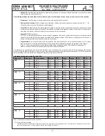
Note:

The SID/ PID for the slots configured (the programs and channels) is automatically allocated according to a fixed pattern. Inserting 

details of the device in the cascade and the number of the cascade ensures that the values will not overlap. If “outside” transport 

streams are being processed at the ASI input port, care must be taken to ensure that if the SID/ PIDs of any external and internal 

program streams overlap, the internal program streams have priority. Any “external” program streams with the same names will be 

blocked at a filter and not fed into the output port.

Operating several cascades within a network (a head end)

To get unique service ID‘s if there are several cascades in one head end, an offset is automatically added for the parameter “cascade

number within network” (CN

o

):

Cascade N

o

1

2

3

4

5

6

7

8

Offset

0x00

0x04

0x08

0x0C

0x80

0x84

0x88

0x8C

Table 4: Offset for the service ID‘s if several cascades are operated in a network

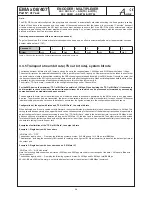
3.3.5 Transport stream bit rate (TS out bit rate), system bit rate

The transport stream bit rate at the ASI output port can be set in the range between 1,024 kbps and 214 Mbps with steps of 1 kbps.

The output bit rate can be selected independently of the input bit rate at the ASI input port. However, care must be taken to ensure that

the entire volume of data is transmitted, including the DVB channels generated additionally by the EMA device. It should be noted that 

the transport stream at the ASI input may contain components with a fluctuating data rate. When estimating the bandwidth which will be

necessary for the transmission of newly generated programs, this should be borne in mind.

The bit rate (“TS-Out bit rate”) is selected in the configuration settings under “Channel Mux“.

For the EMA device, the maximum “TS Out Bit Rate“ possible is 214 Mbps. When deciding the “TS Out Bit Rate“ it is necessary 

and important to check what is the maximum transport stream bit rate which can be processed or forwarded by succeeding 

components such as modulators and upconverters.

The bandwidth (bit rate) which is available can be distributed across the channels generated by the EMA device in any proportions 

de-sired. The more channels are transmitted, the lower is the available system bit rate (slot bandwidth) for each channel. Whenever 

individual settings are made, care should be taken to ensure that the figures entered into the configuration mask make sense.

Configuration of the system bit rates and “TS-Out Bit Rate”, the output bit rate

When delivered and if reset is carried out with firmware, the system bit rates (slot bandwidth) of each channel will be set to 6 Mbps. This 

setting should be seen simply as an upper limit and can be varied according to the content of the data being transmitted. It is possible to 

adjust the figures for each channel according to need. The “TS-Out Bit Rate”, which is the data output rate, is preset to 38 Mbps, which 

gives enough scope for reliable operation as long as the “ASI Main IN”, the input port, is deactivated. The output rate must be decided 

in relation to the content being added, with a safety margin of at least 10 per cent, since it is not possible definitely to exclude swings in 

the data rate taking it over the upper limit.

Examples of estimation of the “TS-Out Bit Rate”, the output bit rate

Example 1: Single device with 4 encoders

“ASI Main IN“ = “OFF“

The encoder input ports A ... D employ the following system bit rates:  3x 6 Mbps and 1x 10 Mbps, total 

28

 Mbps

This allocation, including the necessary 

10%

 reserve for safety, gives a figure of 

31

 Mbps (minimum) to be set as the data output rate at

the output port.

Example 2: Single device with 4 encoders and an “ASI Main IN“

“ASI Main IN“ = “MUX with intern“

Here the incoming data stream has a bit rate of 50 Mbps, and 36 Mbps are used for the transport of the data. 14 Mbps are filled with

“empty packets”.

The encoder input ports A ... D employ the following system bit rates: 2x 4 Mbps and 2x 8 Mbps, total 

24

 Mbps

36+24=

60

, plus 

10%

 safety margin, so that the data output rate at the output port is 

66

 Mbps (minimum).

Summary of Contents for EMA 308 9173.81

Page 1: ...Professional Headend Solutions Operating instructions EMA 308 407 408 EMA 508 608 708 Part No 917x xx ENCODER MULTIPLEXER ASI SDI A V ASI TS IP TS ASI HDMI ASI TS IP TS ...

Page 2: ...Menu Output 17 3 3 2 3 1 Output MUX TTX EIT 17 3 3 2 3 2 Output TS Out 17 3 3 2 3 3 Output Expert Mode 19 3 3 2 4 Menu Streaming 20 3 3 2 4 1 Streaming Interface 20 3 3 2 4 2 Streaming Str 1 20 3 3 2 5 Menu Status 21 3 3 2 5 1 Status Pg 190 21 3 3 2 5 2 Status Pg 192 21 3 3 2 5 3 Status Pg 196 22 3 3 2 5 4 Status Pg 197 22 3 3 2 5 5 Status Pg 198 23 3 3 3 Transcoder operating modes 23 3 3 3 1 EMA ...

Page 3: ... are only allowed when the EMA is disconnected from the power supply Follow the provisions of DIN EN 50083 in particular DIN EN 60728 11 1 regarding safety must not be ignored The device are delivered under protection classification I It is absolutely necessary to insert the mains plug into a fused socket Warning When connecting external video sources that do not match the ground potential of the ...

Page 4: ...wer supply EMA 408 9174 81 SDI ASI TS MPEG 2 ASI TS IP TS H 264 AVC SD HD A V ASI TS IP TS H 264 AVC SD 85 264 V 110 370 V Power supply 1 EMA 408 9174 82 SDI ASI TS MPEG 2 ASI TS IP TS H 264 AVC SD HD A V ASI TS IP TS H 264 AVC SD 36 75 V Power supply 1 EMA 408 9174 91 SDI ASI TS MPEG 2 ASI TS IP TS H 264 AVC SD HD A V ASI TS IP TS H 264 AVC SD 85 264 V 110 370 V Power supply 1 Customer variant EM...

Page 5: ...es and associated services PAT PMT and SDT A NIT is generated but will not contain any network specific information A subsequent modulator adjusts the adaptation of the NIT 1 4 Multiplexer Re multiplexer PID filter For processing the incoming ASI transport stream a multiplexer has been integrated into the EMA device On condition that the transport steam provides enough transmission capacity or add...

Page 6: ...deactivated LED flashing ASI signal isn t recognised at the input port LED on ASI signal is recognised at the input port Stream port IP stream port RJ45 Ethernet 10 100 1000 UDP RTP 2 2 Rear view Fig 2a Rear view of the devices EMA 308 407 408 608 FACTORY SET Fig 2b Rear view of the devices EMA 508 708 2 2 1 Input and output ports VIDEO A B C D Video input port FBAS SDI configurable AUDIO A B C D ...

Page 7: ...Functionality mono dual stereo 7 n c 6 SPDIF 1 stereo dual mono not in use channel B right channel 3 1 left channel channel A signal 5 4 Pin 2 shielding Fig 3 Pole allocation audio socket 1 SPDIF input of the digital audio signal only available if there are H 264 AVC encoder modules EMA 407 EMA 408 2 2 3 EMA variants with 48 V DC power supply The EMA is also offered with a 48 V DC PSU EMA x08 917x...

Page 8: ...ing table EMA 308 EMA 407 EMA 408 508 608 708 IP address 192 168 2 86 IP netmask 255 255 255 0 IP gateway 0 0 0 0 SNMP trap IP 0 0 0 0 Login password neu IP address 192 168 2 86 IP netmask 255 255 255 0 IP gateway 0 0 0 0 SNMP trap IP 0 0 0 0 Login password neu IP address 192 168 2 86 IP netmask 255 255 255 0 IP gateway 0 0 0 0 SNMP trap IP 0 0 0 0 Login password neu General Selections PSI mode DV...

Page 9: ... the computer System requirements PC laptop with an Ethernet interface 10 100 Mbps Internet browser such as Windows Internet Explorer Mozilla Firefox or similar Making the connections The EMA device has to be connected to PC network using an Ethernet cable Use a crossed link cable for a direct connection to a PC The IP address of the EMA is 192 168 2 86 on delivery In order to access the web inter...

Page 10: ...g at these you can switch from one to the other sub menus In each menu a Help button in the lower part of the user interface leads into a separate bilingual help window German English The button Save to device sets and saves the done settings on the device Load from device fetches the on the device saved data into the web interface Anything pre set under Factory Setting is typed with an underline ...

Page 11: ... error Reload Parameter EncC no input Default error EncC error EncD no input EncD error 3 3 2 1 2 System General Fig 8 Standard operating mode EMA 408 508 608 708 Setting the operating mode is based on the equipped hardware Changes in this section need to be saved Save to Device to adapt the relevant configuration entries PSI Mode DVB ATSC Multiplexer mode according to the national transmission st...

Page 12: ...g see below parameter Slot A D special operation see section 3 3 3 Transcoder operating mode TS Player Option OFF Play from HDD If a hard disk player is integrated the feature can be activated with Play from HDD Mapped Channel Dynamic PMT OFF ON ON Allows a PMT Program Map Table influence in connection with option TS player for example for switching transmission windows in existing programs IP Out...

Page 13: ... Cycl cyclical synchronization of the decryption process ON PMT synchronization of the decryption process with a dynamic PMT change MPEG 2 Audio Frames per PES Block 1 4 8 Encoder parameter of audio block size FAN ON above Temperature in C 0 50 100 Switching threshold of the device fan 3 3 2 1 4 System Maintenance Fig 10 help functions Set Password The password for the configuration access Rules m...

Page 14: ...figuration of the device is reset to the factory default settings There is no available transport stream signal for 10 seconds The IP address will be preserved Note The Factory setting button on the rear of the device changes the IP address to 192 168 2 86 and the password to neu Activate Option Chargeable software options can be enabled here The acquired activation code must be entered here Fig 1...

Page 15: ...r each imported or transformed program The program name is displayed on the terminal equipment TV The program name must be unique and may exist only once in a cascade of encoders The maximum length is 16 characters Program Language deu eng Identifies the language for the audio data stream and teletext It should correspond to ISO 639 2 4 Video System PAL SECAM 50 Hz NTSC 60 Hz OFF Digital Radio OFF...

Page 16: ...ugh the in the input soignal included E AC3 signal is applied to the output signal available in EMA 408 508 608 708 Audio Channel Pair SDI 1 2 15 16 When SDI with embedded audio is being transmitted it can be selected an audio signal pair for the processing dB Audio Volume SDI 6 0 6 Decrease or increase the audio level Audio Input Impedance analogue Input impedance switch 600 Ω 10 kΩ Audio Input L...

Page 17: ...tion TS Output Mode Continuous Burst Continuous Mode All the bytes in the output stream have a fixed temporal distance from each other The maximum data rate in this mode is 98 Mbps Burst Mode All bytes of a packet are sent without a space as a burst 27 MHz The bitrate is enforced by the distance between the packets Possible is a maximum of 214 Mbps Note For an active IP output only the continuous ...

Page 18: ...number to distinguish equipment installed cascade within a transmission network It must be the same number for all devices of a cascade and it serves to generate unique program numbers designated by service ID chapter 3 3 4 2 Device within Cascade 1 8 Device number to distinguish the installed devices within a cascade It is used to generate unique program numbers service ID and PID s automatically...

Page 19: ...a factor without any influence a semicolon openes the comment section Values can be decimal hexadecimal and expressed as a byte value with A The activation of a script is done by pressing the Send Script button Changed values can be reviewed at the transport stream output The basic function can be checked via the status page 190th In the lower part of the table of the error status of the script pr...

Page 20: ...10 78 port 6200 with UDP protocol FEC mode for UDP without functionallity present following information are applied from the TS EIT table service selection 0 applies all services contained in the ASI TS multi program transport stream MPTS TS ID 0 ID remains unchanged Network ID 0 ID remains unchanged user data rate 0 TS out bit rate is adopted unchanged into the IP stream 0 65535 max User Datarate...

Page 21: ...echnical information and status indications for service and remote maintenance 3 3 2 5 1 Status Pg 190 Here is a overview of the bit rates at the respective inputs and outputs of the device Fig 24 overview of the bit rates 3 3 2 5 2 Status Pg 192 This page contains the display of the transport stream parameters Fig 25 transport stream parameters ...

Page 22: ...lots A D Fig 26 Slot modes 3 3 2 5 4 Status Pg 197 This displays an information and function overview of each device part z B display disk fan system status z B device temperature offset time network address the serial number of the device and the software version of each component Fig 27 Information about the device IP frontend software Device software Baseboard software Encoder A D software ...

Page 23: ...ing of DVB signals Per combinations of the function groups the following transcodings each with a H 264 AVC encoder are possible MPEG 2 HD H 264 AVC HD MPEG 2 HD H 264 AVC SD MPEG 2 SD H 264 AVC SD Note Up scale funktions for the generation of HDTV signals from SDTV signals are not available The signals from the demodulator functional group can be supplied via an internal bus to an MPEG 2 encoder ...

Page 24: ... ASI BNC DIN Slot C ASI BNC DIN Slot D ASI BNC DIN BNC FIFO RAM BNC Selection ASI IN Module bus EMA 408 Transcoder ASI IN ASI IN ASI IN ASI IN ASI OUT Service filter ASI input is activated Encoder in slot A is set to transcoder operation mode Main ASI IN is provided as internal signal source at the encoders Input signal of the encoders in slot A is set to Intern TS from the TS the MPEG 2 HD progra...

Page 25: ...Slot A ASI BNC DIN Slot B ASI BNC DIN Slot C ASI BNC DIN Slot D ASI BNC DIN BNC FIFO RAM BNC Selection ASI IN Module bus EMA 407 Decoder ASI IN ASI OUT Service filter Encoder Decoder Encoder H 264 AVC MPEG 2 H 264 AVC MPEG 2 Encoder in Slot B is set to signal feeding internal ASI main input is active and is provided to the encoders as internal signal source The H 264 AVC HD service SID 45 is passe...

Page 26: ...Every device is capable of adding 4 new programs services to the existing DVB transport stream as long as there is enough transport stream capacity or extendibility If devices have been completely individualised in their basic settings each new service would be added as a transponder in its own right To ensure the newly added services belong together it is possible to link up to 8 devices in a log...

Page 27: ...nequivocal in meaning and should therefore be changed to represent the actual situation The information on cascades and positions which has been set in the configuration will be the basis for the distribution of the transport stream over the individual programs or services and of the automatic allocation of neutral program names and of A V PIDs and service IDs in ascending order It is possible to ...

Page 28: ...ant to check what is the maximum transport stream bit rate which can be processed or forwarded by succeeding components such as modulators and upconverters The bandwidth bit rate which is available can be distributed across the channels generated by the EMA device in any proportions de sired The more channels are transmitted the lower is the available system bit rate slot bandwidth for each channe...

Page 29: ...sing the recessed Factory setting key which restores settings to what they were on delivery of the device 3 4 4 Re set to status on delivery Factory settings The following 3 possible ways of restoring the status on delivery A Factory setting using the user software HTML page This will only be possible if the IP configuration for the device is known including network address subnet mask and the dev...

Page 30: ...0 It is only possible to enter or change IP addresses into the HCB x00 directly This cannot be done from the html user interface Warning If multiple EMA devices are being integrated it is important to note that the HCB x00 will search in the network for any IP address N with the lowest value and will then search for nine more with ever higher addresses N 1 N 9 In consequence the maximum number of ...

Page 31: ...ream DVB ASI with H 264 AVC HD SD Input format 720x576 50i 720x480 60i 1280x720 50p 59 94p 60p 1920x1080 50i 59 94i 60i Compression MPEG 2 MP ML according ITU T Rec H 262 ISO IEC 13818 2 8 H 264 AVC MP L3 0 HP L4 0 according ITU T Rec H 264 ISO IEC 14496 10 9 System bit rate slot bandwidth individually per channel slot adjustable 1 024 15 000 kbps 1 024 20 000 kbps Encoder audio compression MPEG 1...

Page 32: ...Control port IP output rear side Ethernet 10 100 Base T RJ 45 Protocols UDP IP Output data rate 20 Mbps Remote control Settings data Ethernet interface UDP IP Cascade system Up to 8 devices can be combined into a cascaded system to form a DVB transport stream using the ASI interface Extra functions Teletext VPS WSS Transparent feed of teletext signals conversion and onward transmission of VPS und ...

Page 33: ...rate Digital bandwidth for audio transmission element of the system bit rate The higher the value the better the transmission quality but it may slightly limit the video bit rate Audio mode Options for the audio channels to be transmitted The options are stereo joint stereo mono dual channel Use VPS The relevant option is entered unchangeably into the EMA coding It will be transmitted with the add...

Page 34: ...uration values which have been set for the EMA device These parameters are read using Load and stored using Save SDI Serial Digital Interface for digital uncompressed video signals 270 Mbps transmission via BNC cables audio data can be embedded SDT Service Description Table This contains the programs offered and relevant details of broadcaster Serial number The 5 digit device serial number This co...

Page 35: ...ased DVB Services over IP Based Networks Ver 1 4 1 2009 08 04 7 SMPTE 2022 1 Forward Error Correction for Real Time Video Audio Transport Over IP Networks 2007 8 ISO13818 2 2000 Information technology Generic coding of moving pictures and associated audio information Video 9 ISO IEC 14496 10 2012 Information technology Coding of audio visual objects Part 10 Advanced Video Coding 6 Document history...

Page 36: ...irms that the mentioned products meet the guideline s of the Council for the approximation of legislation of the member states Electromagnetic compatibility 2004 108 EC The following standards are met DIN EN 50083 2 2007 04 EN 50083 2 2006 06 Low voltage guideline 2006 95 EC The following standards are met DIN EN 60950 1 2006 04 EN 60950 1 2006 11 Information technology equipment Safety Restrictio...

Reviews: