ZYNQ Ultr FPGA Board AXU2CGA/B User Manual
25 / 29
Amazon Store: https://www.amazon.com/alinx
Part 16: DIP Switch Configuration
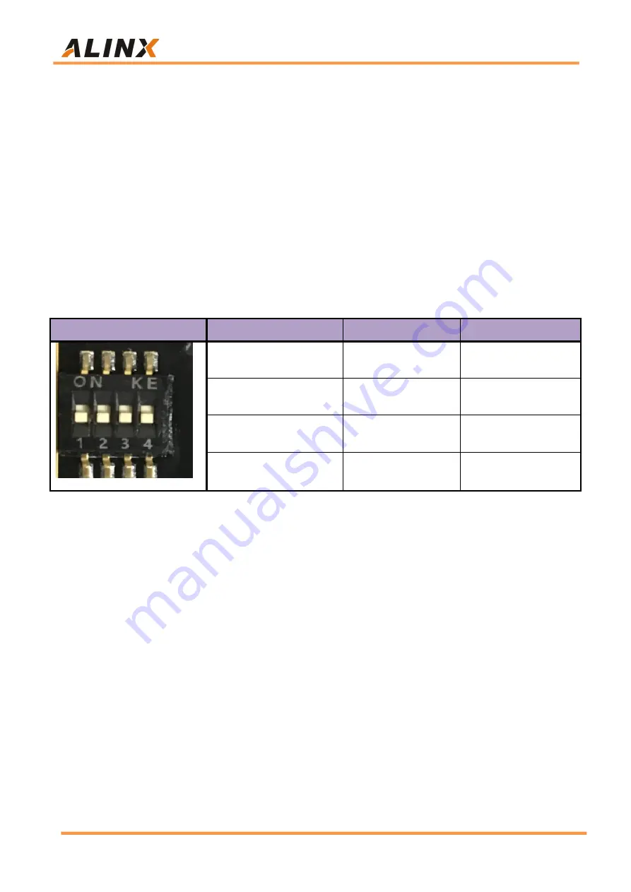
There is a 4-digit DIP switch SW1 on the FPGA development board to
configure the startup mode of the ZYNQ system. The AXU2CGA/B system
development platform supports 4 startup modes. The 4 startup modes are
JTAG debug mode, QSPI FLASH, EMMC and SD2.0 card startup mode. After
ZU3EG chip is powered on, it will detect the level of (PS_MODE0~3) to
determine the startup mode. The user can select different startup modes
through the DIP switch SW1 on the expansion board. The SW1 startup mode
configuration is shown in the following table 16-1.
SW1
Dial Position
(
1
,
2
,
3, 4
)
MODE[3:0]
Start mode
ON
,
ON
,
ON
,
ON
0000
PS JTAG
ON
,
ON
,
OFF ,ON
0010
QSPI FLASH
ON
,
OFF
,
ON
,
OFF
0101
SD Card
ON
,
OFF
,
OFF
,
ON
0110
EMMC
Table 16-1: SW1 startup mode configuration
Part 17: LEDs
There are 4 user indicator lights, 4 user control KEYs and a reset KET on
the AXU2CGA/B board. 4 user indicators and 4 user KEYs are all connected to
the IO of BANK24. The schematic diagram of the LED light hardware
connection is shown in Figure 17-1:


