W 3 S E R I E S
H I G H P R E S S U R E A I R C O M P R E S S O R
©ALKIN COMPRESSORS
11
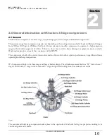
The W3 series compressors are equipped with radiator between the 1st & 2nd stage cylinders and finned tube intercooler
between the 2nd and 3rd stage cylinders and stainless steel aftercooler downstream the 3rd stage cylinder. A moisture trap
(or condensate separator) is installed downstream the 2nd stage intercooler and downstream the aftercooler. Each of these
moisture traps is connected to automatic drain valves that periodically open and drain the condensate in these traps. The
opening intervals and duration is set by a time control relay found in the electrical control panel of the compressor (see the
controls section). This time relay can be adjusted for both functions.
A safety valve is installed between each stage and after the final stage to protect the system against an unexpected pressure
rises due to a malfunctioning valve or component. These safety valves must be inspected periodically to insure proper
operation and set pressure verification (see the
maintenance schedule
for inspection periods).
The W3 series compressors incorporate stainless steel valves on all 3 stages. They are designed to have an unobstructed
passage of air with no pressure loss; they are easy to maintain and replace. Particular attention must be paid to valve
maintenance, as these valves are the basis for proper operation of the compressor package. Do not use oils other than the
recommended oils
in this manual for keeping the valves clean and free of carbon collection. Unsuitable oils will cause
carbonization which will collect on the valve discs and springs, resulting in improper sealing of valves, This will increase
the operating temperatures, generating a chain reaction for further deterioration of the oil and valve operation.
Lubrication is created by dipstick found in the bottom of the 4
th
stage connecting rod. While the crankshaft rotating, the
connecting rod reciprocates and the dipstick enters the oil bath in the bottom of the crankcase; while coming out of this
oil bath, the dipstick splashes oil to the moving parts of the compressor. Efficient oil wiper rings control the economical
lubrication of the system.
See the process and instrument diagram to study the general system layout and operation sequence.
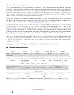
2.2 Thechnical Specifications
Model
Power
Outlet
Working Pressure
Purifier
W3 High Pressure Air
Compressor
30 kw
Single
250 Bar
P61
Performance Data
Model
Max. Working
Pressure
FAD
Power
RPM
Cylinder Bore
Stage
BAR
PSI
Lt/min Cfm HP kW
W3 High Pressure Air
Compressor
250
3625
1350
47
40 30
950
160mmx 2
3/4
”x25mm
3
Stage Pressures
Exit Pressure
1st Stage
2nd Stage
3nd Stage
Bar
Bar
Bar
250 bar
Min.2
Max.5,5
Min. 20
Max. 38
250
Summary of Contents for W3 Series
Page 1: ...W3 SERIES HIGH PRESSURE AIR COMPRESSORS...
Page 2: ......
Page 4: ......
Page 6: ......
Page 10: ...W 3 S E R I E S H I G H P R E S S U R E A I R C O M P R E S S O R ALKIN COMPRESSORS 5...
Page 14: ...W 3 S E R I E S H I G H P R E S S U R E A I R C O M P R E S S O R ALKIN COMPRESSORS 9...
Page 26: ...W 3 S E R I E S H I G H P R E S S U R E A I R C O M P R E S S O R ALKIN COMPRESSORS 21...
Page 30: ...W 3 S E R I E S H I G H P R E S S U R E A I R C O M P R E S S O R ALKIN COMPRESSORS 25...


