W 3 S E R I E S
H I G H P R E S S U R E A I R C O M P R E S S O R
©ALKIN COMPRESSORS
17
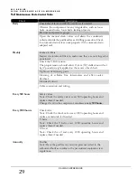
-Flywheel-side panel not properly placed in its place
-Phase Protection Relay tripped
-Fan motor overload tripped
-Motor overload tripped
-High discharge air temperature
-High rotor winding temperature
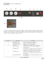
Low Oil Level LED
If the LED is lit, it indicates that the oil in the
compressor crankcase has diminished.
5
ON Button (Green)
Turns the compressor on
Reset Button (Red)
Turns the compressor off
6
Digital Thermostat
Turns the compressor off when the temperature of
the compressor outlet air reaches to the set value
7
Temperature Indicator
Indicates the compressor outlet temperature
8
Set Key
Enables to adjust the set value for the compressor
outlet temperature. Set Key is pressed and hold for
this procedure.
9
Adjusting Keys
Enables to reduce or increase the value when
adjusting the set value
10
1
st
Stage Pressure Gauge
Indicates the first stage compressor pressure
11
2
nd
Stage Pressure Gauge
Indicates the second stage compressor pressure
12
3
rd
Stage Pressure Gauge
Indicates the third stage compressor pressure
13
Main Switch
It is the main member that turns the power to the
compressor on/off
2.5 Description of Controls
2.5.1 Compressor Controls
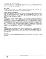
The W3 Series compressor may operate with the following two controls:
Automatic Start
–
Stop Control:
This is the standard control type for all single pressure compressor systems. With this type of control, once the
compressor is manually started, it will run till it reaches the high set pressure where is will automatically stop (the
pressure where the motor will cut-out); after the pressure drops to the low set-pressure (the pressure where the motor
will cut in), it will automatically re-start. This control system is standard on all single pressure compressors.
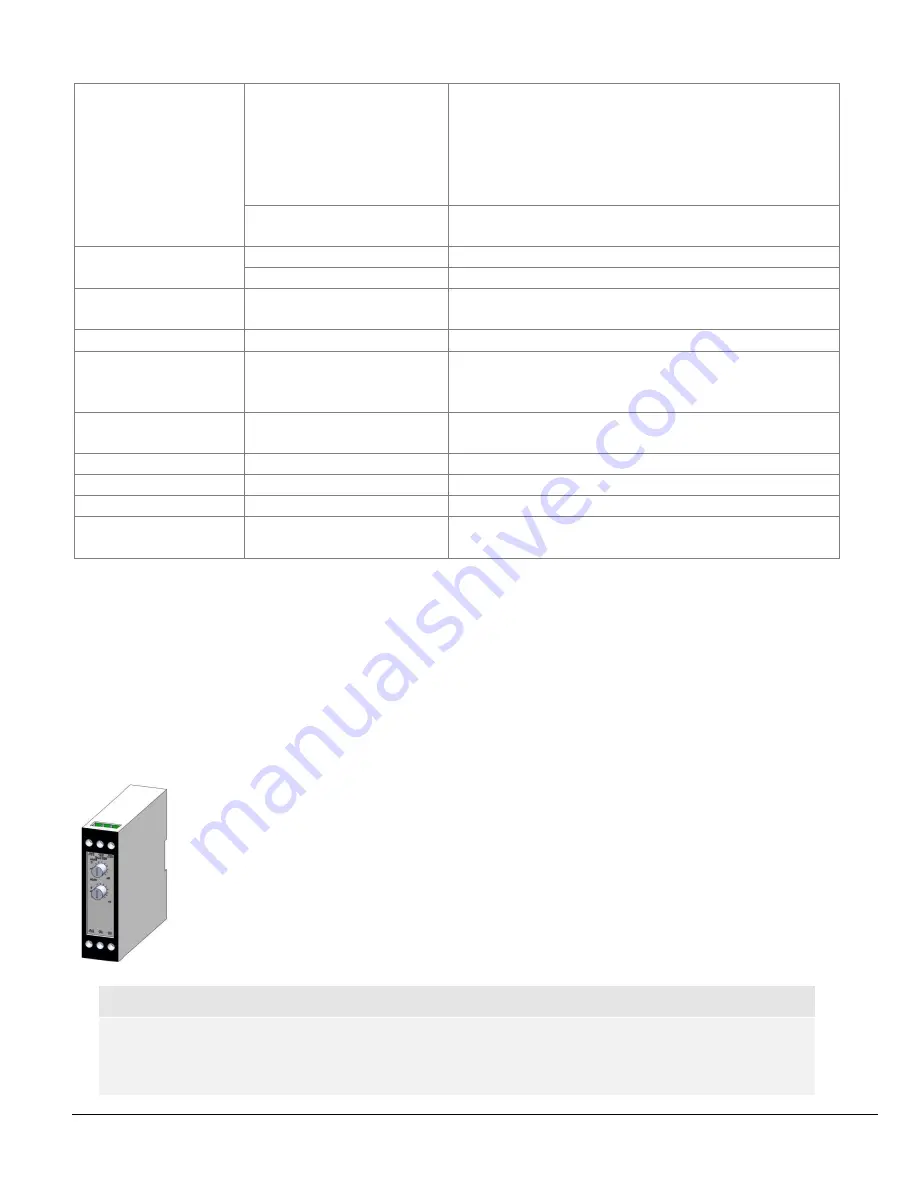
Drain Control:
W3 Series compressors can be automatically drained by automatic drain valves. These drain valves
are controlled by 3 way Solenoid Valve which is normally closed. This solenoid valve supplies or
cuts the control air on the drain valves, thus letting them to open or close. The solenoid valve itself
is controlled by a timer installed in the electrical panel. The dual time adjustment on this timer
allows to adjust the time period (t1~7 min) which the solenoid will remain energised (=the drain
valve will remain closed), and the duration( t2 ~ 6 seconds) during which the solenoid will be de-
energised (=the drain valve will open and perform the drain function).
Important !
Do not change the factory settings of the drain times and durations. Consult the factory if you need to
change the settings.
Summary of Contents for W3 Series
Page 1: ...W3 SERIES HIGH PRESSURE AIR COMPRESSORS...
Page 2: ......
Page 4: ......
Page 6: ......
Page 10: ...W 3 S E R I E S H I G H P R E S S U R E A I R C O M P R E S S O R ALKIN COMPRESSORS 5...
Page 14: ...W 3 S E R I E S H I G H P R E S S U R E A I R C O M P R E S S O R ALKIN COMPRESSORS 9...
Page 26: ...W 3 S E R I E S H I G H P R E S S U R E A I R C O M P R E S S O R ALKIN COMPRESSORS 21...
Page 30: ...W 3 S E R I E S H I G H P R E S S U R E A I R C O M P R E S S O R ALKIN COMPRESSORS 25...

