W 3 1 S E R I E S
H I G H P R E S S U R E B R E A T H I N G A I R C O M P R E S S O R
©ALKIN Kompresör Sanayi ve Ticaret Limited Şirketi
22
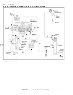
1.4 Principles of Operation
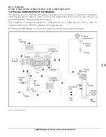
The P & I diagram have to be reviewed carefully to understand the principle of operation.
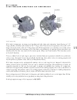
The air is drawn at atmospheric pressure, through the inlet filter into the 1
st
stg. cylinder on the up-stroke of
the piston. The up-stroke motion of the piston will cause compression and the air will be forced out of the
cylinder through 1
st
stg. discharge valve. Air will then pass through the intercooler tubes between the 1
st
and
2
nd
stg. and into the 2
nd
stg. compression chamber. Here, the air is compressed to the 2
nd
stg. compression
level and forced through the 2
nd
stg. 2
nd
stg. inter water sep 3
rd
stg. inlet valve into
the 3
rd
stg. cylinder. Here, the air is compressed to the final pressure level and forced out to the aftercooler,
oil & water separator (pre-filter), than passing through a check valve enters the purifier chamber, where it is
purifier and prepared to be used for breathing purposes. A priority (or minimum pressure valve) is installed
downstream the purifier; this valve prevents the air to exit the purifier until the pressure builds to
approximately 150 bar, a pressure level where the purification process is more efficient than at lower
pressures. The air is than ready to be directed to a filling panel and with proper connections to the cylinders
to be filled. The intercoolers and the aftercoolers are designed to dissipate the heat generated from the
previous compression cycle, reducing the air temperatures, allowing the water vapor to condensate and settle
in the bottom sections of the water separators. The water separator and the oil & water separator (prefilter)
are equipped with either a manual drain or, an automatic drain valve, or both.
The drain valve is a 3 way pneumatic valve controlled by a 3-way solenoid valve. This solenoid valve sends or
removes the control air from the drain valves, thus letting them to open or close. The solenoid itself is
controlled by a sequential timer relay in the electrical panel. The dual time adjustment on this relay allows to
adjust the duration during which the solenoid will remain energized (=the drain valve will remain closed), and
the length of time during which the solenoid will become de-energized (=the drain valve will open and
perform the drain function).
The condensate water should be drained by using the manual drain valve located below purifier, when the
compressor is operating, at every ten minutes. This should be done even for mariner models with auto drain
feature. Moreover, when the compressor is shut off, this should be done to drain the compressed air in the
purifier.
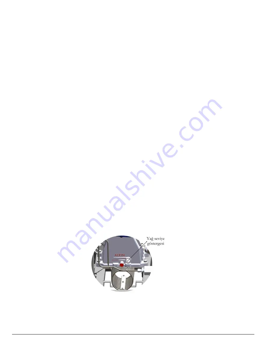
Compressor can be started or stopped with the start / stop button located on the electric panel. Oil level can
be monitored by Oil Level Glass located in the front side of the crankcase. Oil level should be checked daily.
1.5 Lubrication System
Lubrication is performed with splash lubrication system. The stick at the bottom of connecting rod moves in
oil and the connecting rod lubricates the stages by carrying the oil upstream with the oil received from the
crankcase. Replace the compressor’s oil due to maintenance table periods. This is quite important for the
service life of compressor. See the oil replacement introduction for changing the oil.


