A regular maintenance schedule for descaling your
heating coil is essential to insure its longevity.
The frequency of descaling depends upon the amount
of use and the condition of the water.
COIL BACK
PRESSURE CHECK
08-19-04 Z08-02830H
11
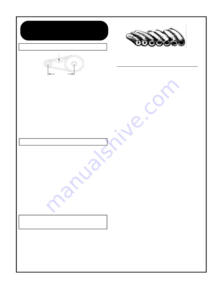
Above is a cross section view showing the progressive liming
of coils.
COIL BACK PRESSURE CHECK INSTRUCTIONS
1. Check the condition of your water pump unloader valve.
Remove the hose and gun assembly from the coil
outlet.
2. Remove any flow restrictions, such as guns and hoses,
from the coil outlet.
3. Install a pressure gauge between the water pump and
coil inlet.
DISCHARGE VOLUME BACK PRESSURE
GPM REQUIRING DESCALING
2-3 GPM
50 PSI
3-4 GPM 75 PSI
4-5 GPM 100 PSI
6 GPM 150 PSI
8-10 GPM 175 PSI
USE A 1000 PSI PRESSURE GAUGE
4. Turn on the water supply. Check the float valve (if so
equipped) to assure float tank is full and the float valve
shuts off securely.
5. Check the position of the ball valve (if so equipped) on
the outlet line of the float tank assuring it is in the open
position.
6. Turn on the switch to the “PUMP” position. If the coil
back pressure reading is above that found in the chart
above then your machine needs to be descaled.
A separate descaling pump is recommended so scale and
other chemicals will not come in contact with your water
pump and causes premature wear.
NOTE: Contact your local dealer for descaling of your unit.
7.
Disconnect the water supply.
8.
Disconnect the electrical supply.
9.
Reinstall the hose and gun assembly.
10. Remove the pressure gauge.
Descaling Instructions are available upon requestask for part
number Z08-00493.
MACHINE
MAINTENANCE
DEFLECTION
SPAN
1.
Deflection for each inch of span between pulley
centers with a 6-pound force applied in the middle of
the span.
EXAMPLE: A 6-pound force applied at the middle of
an 8 inch span should produce a deflection of 8/64
inch or 1/8 inch.
2.
Belts can be tightened or loosened by loosening the
nuts holding the pump assembly to the motor mount.
Then tighten or loosen the j-bolt on the motor mount.
Retighten the pump assembly after the desired tension
is reached.
1.
Remove the spray tip from the gun assembly.
2.
Blow out debris with compressed air from the outside
in. Any debris remaining in the inlet side of the nozzle
should be cleaned out. If lime or chemical scale is
present in the inlet side, the nozzle may be soaked
in descaling solution or replaced. If the tip is worn,
replace with one specified in the GENERAL section
of
MODEL
SPECIFICATIONS
or
MODEL
EXPLODED
VIEW
.
3.
Before replacing spray tip flush the machine per
“FLUSHING”.
4.
Reinstall Spray tip to gun assembly.
BELT TENSION
SPRAY TIP MAINTENANCE
Summary of Contents for 3102 Series
Page 21: ...12 12 02 Z08 00064S ECN 02897 Supersedes 09 00 Z08 00064 7 ...
Page 22: ...09 00 Z08 00064 ECN 02311 7 ...
Page 25: ......
Page 26: ......
Page 37: ......
Page 43: ...4 ...
Page 44: ...14 ...
Page 47: ......
Page 48: ......
Page 50: ......


