9
OPERATOR INSTALLATION
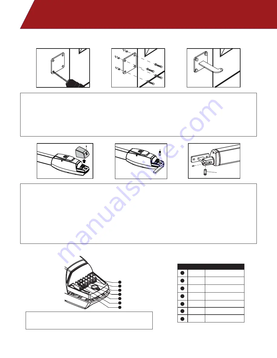
WIRE CONNECTION:
(1) Avoid tension in the cable during open and close cycles.
(2) Always connect the grounding wire (GND)
6
5
3
2
1
no.1
no.2
A
B
4
7
1
White
Yellow
Red
White
Black
+5V
INDEX
COMMON
Limit Switch (Limit 1)
Limit Switch (Limit 2)
1
2
3
4
5
Motor (+)
Motor (-)
6
7
Blue
Green
Use the back mounting plate to have a welding surface when a steel post is not available. Use anchor bolts to
mount the plate to existing surface.
Cut the back mounting bracket to fit the geometry and weld the bracket to the steel post or back mounting plate.
NOTE: A custom mounting plate is required for gates that open to the outside. See “Push to Open” installation
page.
Remove the wire connection cover on the arm and attach the back mounting bracket with the pin.
Release the gate operator and place the pin into the fitting position no.1 and no.2, as shown below. Use the
setscrew to hold pin no.2 in place.
Make sure that the gate operator is mounted in a horizontal position.
Prior to welding the front gate bracket to the gate leaf, make sure to cover the gate operator to prevent any
damage from welding sparks.
Summary of Contents for TORO 24
Page 2: ......


