background image


12 

IMPORTANT! 

Warranty Activation/Installation & Completion Sign Off Sheet 


NOTE: This sheet must be completely filled out and returned/faxed (270) 753-3773 to Scoreboard 
Service Company before your warranty can be activated. 
 
Your Serial Number _______________________________________ 
 
Your Model Number _______________________________________ 
 
Date Purchased       _______________________________________ 
 
Sales Agent             _______________________________________ 
 
Person Authorizing Purchase (title) ____________________________ 
 
Date Installation Completed   _________________________________ 
 
Company or Person Responsible  
For Installation (address/phone number) ________________________ 


This document confirms that the installation for the 26” x 26” Basketball Shot Clocks has been 
completed. All structural, wiring, and power requirements have been met. This unit has been 
tested in scoring and diagnostic modes, ensuring the functionally of the unit. 
 
 
________________________________ 
Scoring/timing equipment responsible party 
 
 
________________________________ 
Installer 
  
So that we may better serve you, please have this information available in the event you need to 
call technical support.  Technical Support: 1-800-411-3136


Summary of Contents for ALS-200LED

Page 1: ...1 INSTALLATION INSTRUCTIONS FOR MODEL ALS 200LED SHOT CLOCKS www allstarscoreboards com...

Page 2: ...irements 4 MOUNTING THE SHOT CLOCKS ON A WALL 5 SUSPENDING THE SHOT CLOCKS 6 RUNNING CONNECTING THE CONTROL CABLE 7 For Stand Alone Installations 7 At The Scorekeeper s Location 7 RUNNING CONNECTING T...

Page 3: ...TE Shot clocks purchased as part of an integrated system with scoreboard s are controlled by the scoreboard controller using the hand held shot clock controller This allows a second individual to conv...

Page 4: ...he installed system NOTE For backboard or goal mounting instructions please contact the manufacturer of your goal backboard NOTE The control cable connected to the shot clocks will run from the scoreb...

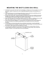
Page 5: ...e 4 Move the clock away from the wall and drill the holes for the anchors Install the anchors in the wall See illustration below for location of mounting flanges and mounting holes 5 Once the anchors...

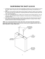
Page 6: ...o 2 separate suspension cables may be attached to the hanging brackets in the top of the unit See illustration below for locations of mounting holes top mounting flange and hanging brackets 4 If the c...

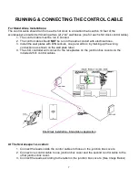
Page 7: ...e wall plates with DIN sockets one per wall box by making up the wiring connections as shown on the wall plate label 4 The LCD controller will connect to the receptacles on the junction box covers via...

Page 8: ...oreboard the control cable will run from the scoreboard to the first shot clock then from the first shot clock to the second 2 If there are two scoreboards one shot clock will be connected to the near...

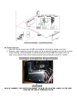
Page 9: ...ntrol cable from the shot clock into the scoreboard through one of the two conduit holes in the top of the scoreboard located directly above the HOME score digit and run it down to the cable terminal...

Page 10: ...ons on how to connect the controller to the scoreboard and shot clocks and for detailed controller operation instructions Connecting cable controlled systems Connect one end of the supplied 20 ft cont...

Page 11: ...turn to game mode press RESET followed by ENTER If at any time during the installation process you have a question to which the answer cannot be found in this manual please call Scoreboard Service Com...

Page 12: ...__________ Date Installation Completed _________________________________ Company or Person Responsible For Installation address phone number ________________________ This document confirms that the in...

Page 13: ...13...

Reviews: