


3
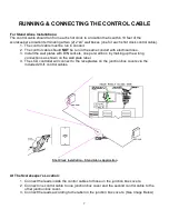
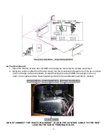
SHOT CLOCK INSTALLATION
NOTE TO INSTALLERS: PLEASE RETURN THIS MANUAL TO THE INDIVIDUAL IN CHARGE OF
THE SCOREBOARD UPON COMPLETION OF INSTALLATION.
The scoreboard and all accompanying accessories have been carefully inspected and tested before leaving the factory.
However, it is possible for damage to have occurred during shipping. Therefore, we ask that you inspect all shipping
containers upon arrival for damage and ensure that you have all of the parts listed below. Check the Shock Watch
sticker on the outside of each of the large packages. Please read and follow the instructions on the Shock Watch
stickers to ensure that there were no hard impacts to the scoreboard during shipping. If you find that damage has
occurred during shipping: 1) accept the shipment from the carrier…DO NOT refuse the shipment, 2) follow the instructions
for filing a freight damage claim found below, and 3) notify the manufacturer immediately.
THE SHOT CLOCK SYSTEM SHOULD INCLUDE THE FOLLOWING PARTS:
(2) 26” X 26” shot clocks, shipped in one (1) section each
(1) Hand held shot clock controller; connects directly to the LCD controller
(1) Customer-specified length of control cable (unless purchased from a separate vendor); to connect the shot clocks to
the scoreboards for integrated installations or directly to the scorekeeper’s location for stand-alone installations
(1) Documentation CD (including installation, operation, maintenance, warranty, and support information)
NOTE: Shot clocks purchased as part of an integrated system with scoreboard(s) are controlled by the scoreboard
controller using the hand held shot clock controller. This allows a second individual to conveniently control the shot clocks
while using only one LCD controller.
Shot clocks purchased for stand-alone installation (to be operated independently of scoreboard(s) should also
include the following parts):
(1) LCD controller with DC wall transformer and (3) keypad inserts
(2) Junction box covers with built-in receptacles; to be installed at scorekeeper’s location (one for each shot clock)
(2) 20-ft. control cables; to connect the LCD controller to the junction box covers (one for each shot clock)
(2) 6-ft control cables to connect at shot clock (one for each shot clock)
INSTRUCTIONS FOR REPORTING SHIPPING DAMAGE
Shipping damage must be noted at the time of delivery. Consignee must note “Damaged” on the
Delivery Receipt. Please make notations of the type of damage to the freight and to the packaging.
Ask the delivery driver to call the local terminal to report the freight damage immediately. The shipper
is not responsible for the shipments that are not signed for as damaged upon arrival. Please contact
the manufacturer immediately to report the damage. The shipper is responsible for filing the claim,
unless shipped 3RD Party.
If damage is discovered after delivery, call the delivery company to report the concealed damage and
please call the manufacturer immediately to report the damage. Concealed damage must be
reported within 5 days after delivery date. If the damages are found after this time, the manufacturer
will not be responsible for damage.


