background image


7

RUNNING & CONNECTING THE CONTROL CABLE 


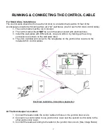
For Stand Alone Installations: 


The control cable should run from each shot clock to a location that is within 10 feet of the 
scorekeeper’s location terminating at two (2) 2”x4” wall boxes (one for each shot clock control cable).  

1.  The control cable must be run in conduit.  
2.  The control cable should NOT be run in the same conduit with electrical lines.  
3.  Install the wall plates with DIN sockets, one per wall box, by making up the wiring 

connections as shown on the wall plate label.  

4.  The LCD controller will connect to the receptacles on the junction box covers via the 

included 20-ft. control cables.  


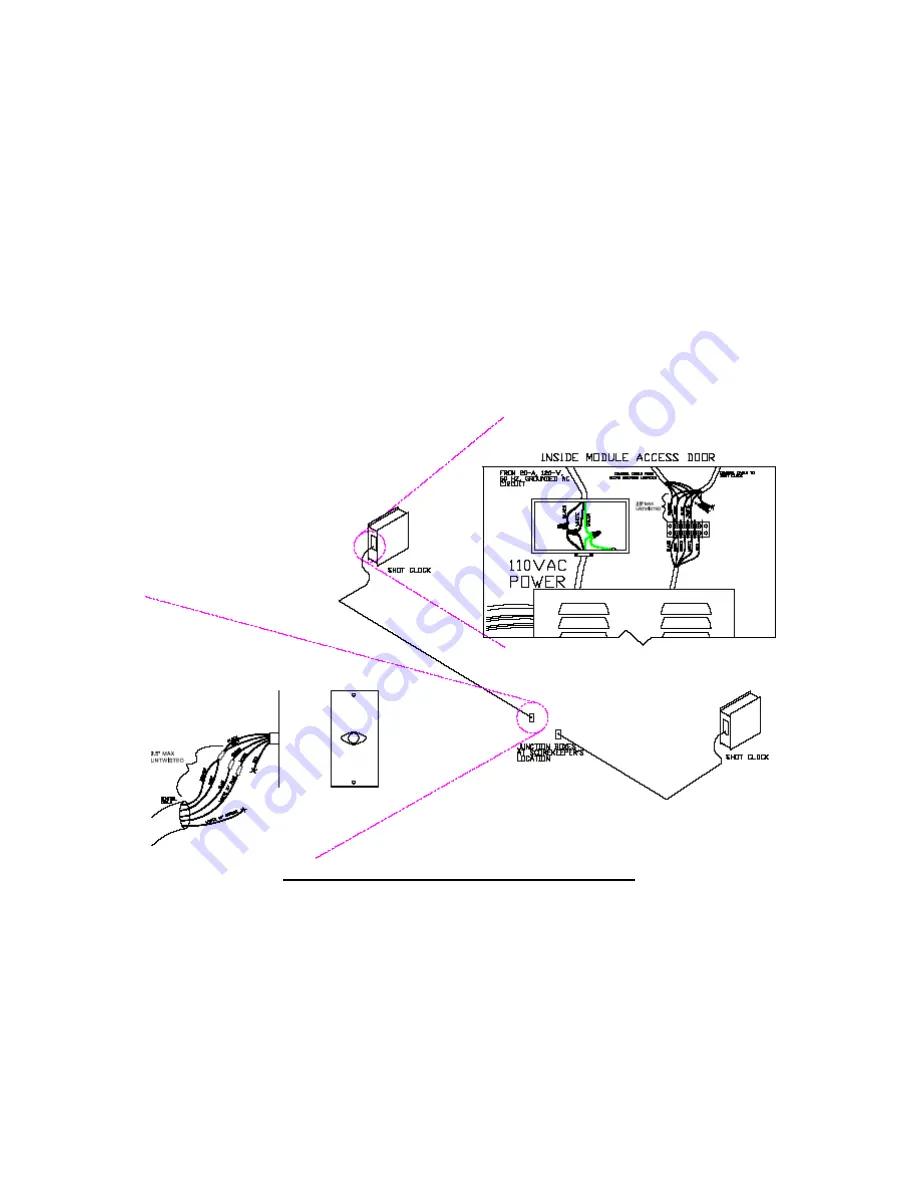
Shot Clock Installation – Stand Alone Application 


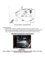
At The Scorekeeper’s Location: 


1.  Connect the leads inside the control cables to those on the junction box covers.  
2.  Connect one control cable to one junction box cover and the second control cable to the 

other junction box cover.  

3.  Connect the leads according to the label on the junction box covers. (See Image Below) 
 

Summary of Contents for ALS-200LED

Page 1: ...1 INSTALLATION INSTRUCTIONS FOR MODEL ALS 200LED SHOT CLOCKS www allstarscoreboards com...

Page 2: ...irements 4 MOUNTING THE SHOT CLOCKS ON A WALL 5 SUSPENDING THE SHOT CLOCKS 6 RUNNING CONNECTING THE CONTROL CABLE 7 For Stand Alone Installations 7 At The Scorekeeper s Location 7 RUNNING CONNECTING T...

Page 3: ...TE Shot clocks purchased as part of an integrated system with scoreboard s are controlled by the scoreboard controller using the hand held shot clock controller This allows a second individual to conv...

Page 4: ...he installed system NOTE For backboard or goal mounting instructions please contact the manufacturer of your goal backboard NOTE The control cable connected to the shot clocks will run from the scoreb...

Page 5: ...e 4 Move the clock away from the wall and drill the holes for the anchors Install the anchors in the wall See illustration below for location of mounting flanges and mounting holes 5 Once the anchors...

Page 6: ...o 2 separate suspension cables may be attached to the hanging brackets in the top of the unit See illustration below for locations of mounting holes top mounting flange and hanging brackets 4 If the c...

Page 7: ...e wall plates with DIN sockets one per wall box by making up the wiring connections as shown on the wall plate label 4 The LCD controller will connect to the receptacles on the junction box covers via...

Page 8: ...oreboard the control cable will run from the scoreboard to the first shot clock then from the first shot clock to the second 2 If there are two scoreboards one shot clock will be connected to the near...

Page 9: ...ntrol cable from the shot clock into the scoreboard through one of the two conduit holes in the top of the scoreboard located directly above the HOME score digit and run it down to the cable terminal...

Page 10: ...ons on how to connect the controller to the scoreboard and shot clocks and for detailed controller operation instructions Connecting cable controlled systems Connect one end of the supplied 20 ft cont...

Page 11: ...turn to game mode press RESET followed by ENTER If at any time during the installation process you have a question to which the answer cannot be found in this manual please call Scoreboard Service Com...

Page 12: ...__________ Date Installation Completed _________________________________ Company or Person Responsible For Installation address phone number ________________________ This document confirms that the in...

Page 13: ...13...

Reviews: