background image

Nome file: 

2018-07-05 PRATIK30 user manual ENG.docx 

Directory: 

C:\Users\Vani\Documents 

Modello: 

C:\Users\Vani\AppData\Roaming\Microsoft\Templates\Normal.dotm 

Titolo: 


Oggetto: 


Autore: 

Utente 

Parole chiave: 


Commenti: 


Data creazione: 

06/07/2018 00:03:00 

Numero revisione: 

Data ultimo salvataggio:06/07/2018 00:04:00 

Autore ultimo salvataggio: 

Vani 

Tempo totale modifica  9 minuti 

Data ultima stampa: 

06/07/2018 00:13:00 

Come da ultima stampa completa 


Numero pagine: 

58 


Numero parole: 

7.304 (circa) 


Numero caratteri:  41.633 (circa) 


Summary of Contents for PRATIK 30

Page 1: ...IN MANUAL BEFORE USING THE LIFT 1 PRATIK Installation use and maintenance ENG USE AND MAINTENANCE MANUAL CAREFULLY READ THE INSTRUCTIONS GIVEN IN THIS MANUAL BEFORE USING THE LIFT TRANSLATION OF THE...

Page 2: ...2 PRATIK Installation use and maintenance ENG EDITION 2018 07 05...

Page 3: ...3 PRATIK Installation use and maintenance ENG EDITION 2018 07 05...

Page 4: ...4 PRATIK Installation use and maintenance ENG EDITION 2018 07 05...

Page 5: ...ty VAT and any other expense not specified in the supply contract are at the purchaser s charge The replacement and repair of parts under warranty anyway do not extend warranty terms The nevertheless...

Page 6: ...ERGENCY LOWERING 5 HANDLING AND INSTALLATION 5 1 TRANSPORT AND UNLOADING 5 2 FOUNDATIONS 5 3 LIFT POSITIONING 5 4 CONNECTING HYDRAULIC PIPES 5 5 ELECTRICAL CONNECTIONS 5 6 HYDRAULIC SYSTEM FILLING 5 6...

Page 7: ...230 400 60 10 5 7 1 Three phase motor power kW HP 2 6 3 5 Motore elettrico 4 poli monofase Volt Hz Amp 230 50 15 9 4 pole single phase electric motor KW HP 2 2 3 Maximum Operating Pressure bar MPa 240...

Page 8: ...rm 3 parallelogram 4 arms 5 arms 6 rubber pads 7 ramps 8 hydraulic cylinders 9 control panel 10 switch emergency 11 up button 12 down button 13 lamp voltage presence 14 buzzer 15 identification plate...

Page 9: ...9 PRATIK Installation use and maintenance ENG EDITION 2018 07 05 1 2 OVERALL DIMENSIONS model C 650 675 675 900 2000 350 2210 3000 MAX FIG 2...

Page 10: ...10 PRATIK Installation use and maintenance ENG EDITION 2018 07 05 1 2 OVERALL DIMENSIONS model L 650 675 675 3720 2000 350 900 3000 MAX FIG 3...

Page 11: ...11 PRATIK Installation use and maintenance ENG EDITION 2018 07 05 1 2 OVERALL DIMENSIONS model I FIG 4...

Page 12: ...nstallation use and maintenance ENG EDITION 2018 07 05 1 2 1 FOUNDATIONS SCHEME INSTALLATION ON THE FLOOR ATTENTION WITHOUT THE REQUIREMENTS IN FIG 5 or 5A NOT STARTED WITH INSTALLATION OF FIG 5 Clk c...

Page 13: ...13 PRATIK Installation use and maintenance ENG EDITION 2018 07 05 1 2 2 FOUNDATIONS SCHEME INSTALLATION ON THE FLOOR FIG 5A VEHICLE ENTRANCE Clk class 20 25...

Page 14: ...14 PRATIK Installation use and maintenance ENG EDITION 2018 07 05 1 2 3 FOUNDATIONS SCHEME INSTALLATION ON THE FLOOR WITH FRAME FIG 5B...

Page 15: ...DISTRIBUTION LOAD DISTRIBUTION 3 5 2 5 di Q Q CAPACITY 3000 KG Q1 1800KG 3 5 DI Q Q2 1200KG 2 5 DI Q Q2 MAX 1200KG 2 5 DI Q Q1 MAX 1800KG 3 5 DI Q Q1 MAX 1800KG 3 5 DI Q Q2 MAX 1200KG 2 5 DI Q RECOMME...

Page 16: ...ance ENG EDITION 2018 07 05 1 4 PICTOGRAMS 1 5 PICTOGRAMS APPLICATION DIAGRAM P1 P2 SOLLEVATORE PER VEICOLI MODELLO PRATIK MARTRICOLA xxxxxxxx VOLT xxx PRESSIONE BAR xxx A xx 2 10 9 8 10 8 3 2 1 10 7...

Page 17: ...se and maintenance ENG EDITION 2018 07 05 1 6 HAZARDOUS AREAS WARNING STRICTLY FORBIDDEN ACCESS INSIDE THE HAZARD ZONE MARKED BY YELLOW LINE DURING THE UP AND DOWN MOVEMENT OF THE LIFT OPERATOR AREA 5...

Page 18: ...safety and health To certify lift compliance with Directive provisions before marketing the manufacturer subjected a machine specimen to the audit of a notified body Lift manufactured in compliance w...

Page 19: ...levelled in all directions You shall compulsorily check that the floor has been constructed to withstand the max allowed loads including the lift on lift resting areas The lift shall be compulsorily...

Page 20: ...out on the equipment All danger signalling stickers present onto the lift shall be compulsorily cleaned regularly or changed The lift shall be compulsorily cleaned and all oil spots on the floor clea...

Page 21: ...any danger The min distance of the hazardous area from the walls of the premise where the vehicle lift is installed shall be at least 70 cm Lighting shall be good but without blinding or intense light...

Page 22: ...t the manufacturer s authorisation 3 5 HAZARDOUS AREAS Before using the lift make sure that no unauthorised people nor animals are present within the hazardous area delimited by the yellow stripe Fig...

Page 23: ...air maintenance and inspection purposes 4 0 INSTRUCTIONS FOR USE CAUTION For lifting of vehicles always use the rubber shims 6 Fig 1B supplied by placing them at the points specified by the vehicle ma...

Page 24: ...e yellow band Fig 8 there are no people or animals The above verifcation must always be made before proceeding with the lowering of the lift because this phase is considered to be particularly hazardo...

Page 25: ...port suspended loads shall not be more than 20 cm from the floor thoroughly respect the following instructions do not proceed in case of doubts or uncertainty The lift is shipped packed onto a pallet...

Page 26: ...unit 10 Fig 7A in the nearby of the footboard P1 as shown in Fig 2 and 3 keeping in mind that the control unit is either positioned on the left side with respect to the platform P1 To place the unit b...

Page 27: ...and 4 1 about the control panel functions and get comfortable at performing the various operations with the lifter discharged 5 6 HYDRAULIC SYSTEM FILLING Pour 6 litres of oil inside tank T Fig 10 Pow...

Page 28: ...BRING THE PLATFORMS TO THE MAXIMUM HEIGHT 1 CONNECT THE PIPES HYDRAULIC 1 2 and 3 AS FROM PICTURE 9 3 REMOVE THE SOLENOID 1 BY ELECTROVALVE YVC1 4 INSERT THE EXHAUST PIPE 3 DIRECTLY INTO THE HOLE THE...

Page 29: ...1 BY ELECTROVALVE YVC2 8 PRESS UP BUTTON PS AND CHECK THAT THE HOSE 3 FIG 11 DISCHARGE OIL 9 REFIT THE SOLENOID 1 TO THE ELECTROVALVE YVC2 FIG 11 FIG 11A 10 RE ASSEMBLE THE DRAIN PIPE 3 IN ITS FITTING...

Page 30: ...n Figs 2 and 3 Replace to regular connections all controller shell with its screws 5 7 1 DEFINITION OF DANGER AREA Delimiting the perimeter of the danger of the machine by painting a band of width equ...

Page 31: ...WEIGHT WITH PACKING 1 KG 370 2 KG 370 3 KG 40 3 2 1 CAUTION HANDLE THE PRESSURE WITH APPROPRIATE MEANS CONSIDERING THE WEIGHT AND DIMENSIONS FIG 13 HANDLING THE INDIVIDUAL PEDANE CORRECTLY AS SHOWN I...

Page 32: ...32 PRATIK Installation use and maintenance ENG EDITION 2018 07 05 5 9 HYDRAULIC CONNECTIONS WITH CONTROL UNIT POSITIONED RIGHT FIG 15...

Page 33: ...33 PRATIK Installation use and maintenance ENG EDITION 2018 07 05 5 9 1 HYDRAULIC CONNECTIONS WITH UNIT LOCATED ON THE LEFT FIG 15A...

Page 34: ...ION 2018 07 05 5 9 2 FIXING THE LIFT TO THE FLOOR ENGINE CONNECTIONS 400V 3Ph ENGINE CONNECTIONS 230 V 3Ph FIG 16 FIG 17 FIG 18 1 DISCESA DI EMERGENZA EMERGENCY DESCENT FIG 16 A 2 IMPORTANT FOLLOW THE...

Page 35: ...g 1A to 0 OFF lift will completely stop working runways shall stop 6 1 2 VOLTAGE WARNING LIGHT 1 Check that the Switch Disconnector 10 Fig 1A is set to OFF 0 turn it if necessary 2 Turn Emergency Swit...

Page 36: ...ntiene l allineamento The lift does not stay aligned POSSIBILI CAUSE POSSIBLE CAUSES INTERVENTI ACTIONS A Switch Disconnector 11 Fig 1 to OFF 0 No power supply Cable connections Burnt out fuses Reset...

Page 37: ...37 PRATIK Installation use and maintenance ENG EDITION 2018 07 05 8 0 HYDRAULIC SCHEME...

Page 38: ...38 PRATIK Installation use and maintenance ENG EDITION 2018 07 05...

Page 39: ...39 PRATIK Installation use and maintenance ENG EDITION 2018 07 05 8 1 WIRING DIAGRAM 230 400V 3PH for brevini EV1 YVD EV2 YVC1 EV3 YVC2...

Page 40: ...40 PRATIK Installation use and maintenance ENG EDITION 2018 07 05 8 2 CONTROL PANEL SCHEME 7 14 8 10 1 2 6 5 4...

Page 41: ...ASF 50VA 0 230 400 0 24 SMC 4003 A MXAA5 6 F2 FUS VETRO 5X20 RAPIDO 2A 250V MXAA6 7 L1 LAMPADA PRESENZA TENSIONE PLS05 PCWL24 MXAA7 8 SB2 PULSANTE SALITA PPRN5NL F1 PCW10 MXAA8 9 PT PROTEZIONE TERMICA...

Page 42: ...42 PRATIK Installation use and maintenance ENG EDITION 2018 07 05...

Page 43: ...rrect operation of the accidental misalignment hydraulic safety devices 5 Check for electric safety devices fc1 and pda correct operation 6 Check for correct automatic alignment at maximum height 7 Ch...

Page 44: ...44 PRATIK Installation use and maintenance ENG EDITION 2018 07 05...

Page 45: ...operation of the accidental misalignment hydraulic safety devices 5 Check for electric safety devices fc1 and pda correct operation 6 Check for correct automatic alignment at maximum height 7 Check of...

Page 46: ...46 PRATIK Installation use and maintenance ENG EDITION 2018 07 05 TAV 1 SCISSORS AND COMPONENTS P1 SIDE...

Page 47: ...47 PRATIK Installation use and maintenance ENG EDITION 2018 07 05 TAV 1 SCISSORS AND COMPONENTS P1 SIDE...

Page 48: ...48 PRATIK Installation use and maintenance ENG EDITION 2018 07 05 TAV 1 SCISSORS AND COMPONENTS P1 SIDE...

Page 49: ...49 PRATIK Installation use and maintenance ENG EDITION 2018 07 05 TAV 2 SCISSORS AND COMPONENTS P2 SIDE...

Page 50: ...50 PRATIK Installation use and maintenance ENG EDITION 2018 07 05 TAV 2 SCISSORS AND COMPONENTS P2 SIDE...

Page 51: ...51 PRATIK Installation use and maintenance ENG EDITION 2018 07 05 TAV 2 SCISSORS AND COMPONENTS P2 SIDE...

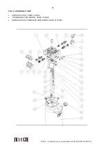
Page 52: ...52 PRATIK Installation use and maintenance ENG EDITION 2018 07 05 TAV 3 HYDRAULIC UNIT HYDRAULIC UNIT CODE 1070041 3 PHASE ELECTRIC MOTOR CODE 1070043 HYDRAULIC UNIT COMPLETE WITH ENGIN CODE K1070041...

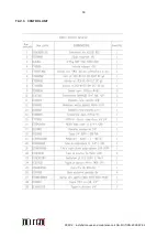
Page 53: ...53 PRATIK Installation use and maintenance ENG EDITION 2018 07 05 TAV 3 CONTROL UNIT...

Page 54: ...54 PRATIK Installation use and maintenance ENG EDITION 2018 07 05 TAV 4 CONTROL PANEL 1 2 3 4 6 7 8 9 10 11...

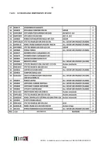
Page 55: ...TORE GENERALE MAIN SWITCH 3 3151121P RELE MOTORE RELAY ENGINE 4 3253392P FUSIBILI FUSES 5 3140271P PONTE RADDRIZZATORE RECTIFIER 6 3253111P FUSIBILE FUSE 7 3241021P LAMPADA PRESENZA TENSIONE LAMP VOLT...

Page 56: ...A C LATO TUBI 3 1054000 SALDATO RAMPA SALITA LUNGA 3A RAMPA SALITA L LATO TUBI 4 1059864 CANALINA PASSATUBI CENTRALE 5 1085644 CANALINA PASSATUBI LATO PONTE 6 0470130 CANALINA ANGOLARE COPRIUTBI 7 108...

Page 57: ...57 PRATIK Installation use and maintenance ENG EDITION 2018 07 05 TAV 6 CONTROL UNIT mod 05 2017...

Page 58: ...58 PRATIK Installation use and maintenance ENG EDITION 2018 07 05 ALLEGRI PIERINO VIA TRASSEGNO 22 36045 LONIGO VICENZA ITALY TEL 39 0444 830 280 CELL 39 335 70 99 649 e_mail info allegrilift it...

Page 59: ...itolo Oggetto Autore Utente Parole chiave Commenti Data creazione 06 07 2018 00 03 00 Numero revisione 3 Data ultimo salvataggio 06 07 2018 00 04 00 Autore ultimo salvataggio Vani Tempo totale modific...

Reviews: