


Allen & Heath 15 XB-14 MK2 User Guide
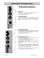
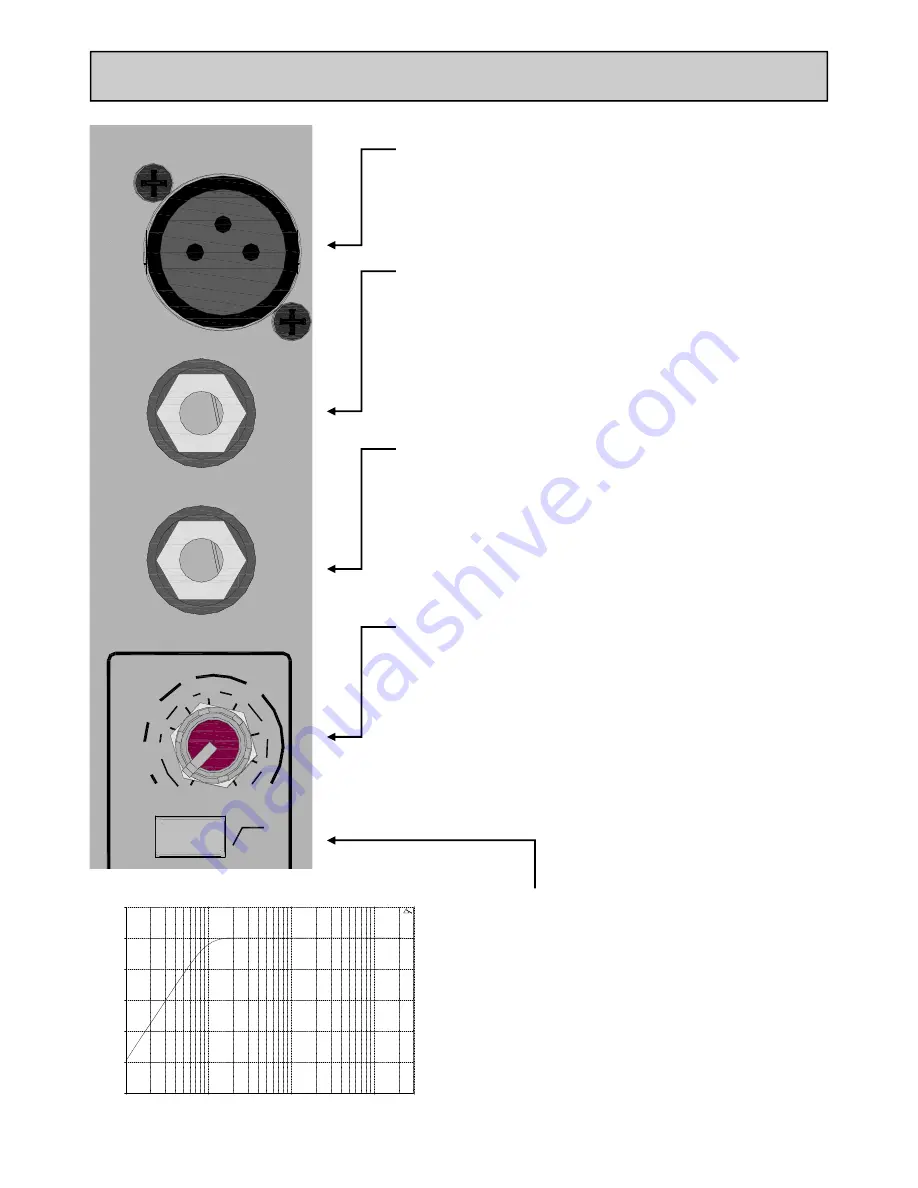
MONO INPUT CHANNEL
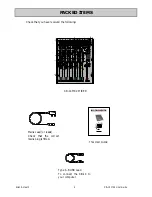
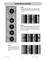
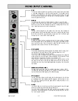
Mic Input Socket
Standard 3-Pin XLR socket wired as Pin 1=Chassis, Pin 2=hot
(+), Pin 3=Cold (-).
Line Input Jack Socket
Standard 1/4” (6.25mm) Jack socket for balanced or unbalanced line
level signals. Wired Tip=Hot (+), Ring=cold (-), Sleeve=Chassis.
The Line input overrides the Mic input, so if you want to hear
something plugged in to the xlr socket, make sure nothing is
plugged into the Line input.
Insert Jack Socket
Standard 1/4” (6.25mm) Jack socket for unbalanced insert send and
return signals. Wired Tip=send, Ring=return, Sleeve=Chassis. Nom-
inal level is 0dBu. The insert point is after the 100Hz filter and be-
fore the EQ.
Gain Control
This adjusts the gain of the input amplifier to match the signal level
of the input. The gain is varied from –6dB (attenuation) to +63dB
for signals plugged in to the xlr socket (Mic Input) and –10dB to
+26dB for signals plugged into the Line input jack.
100Hz High Pass Filter
The Hi-pass filter is used for reducing pop noise and rum-
ble from microphone signals. It is a 2-pole (12dB per oc-
tave) filter with a corner frequency set at 100Hz.
The filter affects signals from both Mic XLR and Line jack
socket.
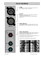
10.00 Hz
100.00
1000.00
10000.00
30000.00
-50.00
-40.00
-30.00
-20.00
-10.00
0.00
10.00
dBr
INSERT
M1
LINE
MIC
100Hz
-6
-10
63 26
GAIN
MIC
0
LINE
10
0
10
20
30
40
50
M1


