Allen & Heath 18 XB-14 MK2 User Guide
TELCO CHANNELS
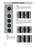
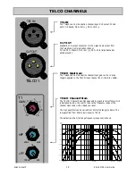
TELCO Input Gain
The Telephone Communication channel input gain control. Varies
the gain applied to the TELCO input channel from –10dB to +26dB.
TEL IN
The Telephone Communication channel input XLR socket. Wired
as Pin 1=Chassis, Pin 2=hot (+), Pin 3=Cold (-).
CLF OUT
Standard XLR output connector for the Clean-Feed output from
the Telephone Communication channel.
Wired Pin 1=Chassis, Pin 2=hot (+), Pin 3=Cold (impedance bal-
anced ground).
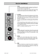
TELCO Channel Filters
The TELCO Channel has a high pass and low pass total cut filter which
is designed to allow the user to reduce the frequency range of the
channel when used with a telephone caller.
The high pass filter can be varied from 20Hz (full range) to 6kHz. The
low pass filter from 20kHz (full range) to 700Hz.
The default position (full range frequency response) is shown.
20.00 Hz
100.00
1000.00
10000.00
30000.00
-30.00
-25.00
-20.00
-15.00
-10.00
-5.00
0.00
5.00
dBr
CLF OUT
TELCO 1
TEL IN
-1O
26
-5
5
10
20
0
GAIN
T1
700Hz
20k
3k
LPF
HPF
20Hz
6kHz
120Hz

