


Allen & Heath 12
XONE:43 User Guide
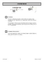
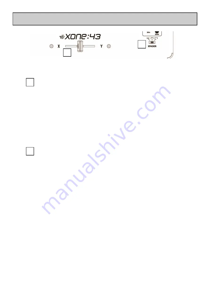
Crossfader
This lets you fade between signals routed to either side, typically to fade
smoothly into a new music track or to creatively layer sounds when scratch or
cut mixing.
The crossfader is a VCA controller which affects the level of signals routed via
the filters. Make sure the switches on the channels you wish to fade are set to
X or Y as appropriate.
CROSSFADER
2
1
Crossfader Curve Control
This control adjusts the crossfader curve between dipped, dipless and fast-cut,
better suited for scratch or cut mixing.
1
2