background image


Allen & Heath                                                                               23                                                                 

XONE:43 User Guide 

REPLACING THE CROSSFADER  

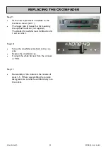
Step 9: 

 

Fit the new replacement crossfader to the 
bracket as shown (slot 1). 

 

The longer (slot 2) beneath is for mounting 
the optional Innofader (not supplied). 


The standard crossfader must be fitted to slot 


1 and not slot 2. 

Step 10: 
 

 

Screw the crossfader plate back to the con-
sole. 

 

Replace the crossfader cap. 

 

Connect the white harness from the connect-
or PCB. 

Step 11: 
 

 

Re-assembly of the console is the reverse of 
steps 1-5.  When re-assembling the console 
take great care to refit the wireform fully into 
the socket. 

Summary of Contents for XONE:43

Page 1: ...Allen Heath 1 XONE 43 User Guide USER GUIDE Publication AP9968_1 ...

Page 2: ...plied warranty of this product Conditions of Warranty The equipment has not been subject to misuse either intended or accidental neglect or alteration other than as described in the User Guide or Service Manual or approved by Allen Heath Any necessary adjustment alteration or repair has been carried out by an authorised Allen Heath distributor or agent The defective unit is to be returned carriage...

Page 3: ...e PACKED ITEMS Check that you have received the following Safety Sheet Important Read this sheet before starting Retain for future reference Mains Lead Check that the correct mains plug is fitted Xone 43 mixer Spare knobs and buttons ...

Page 4: ...re a few minutes familiarizing yourself with the controls and setup procedures outlined in this user guide For further information please refer to the additional information available on our website or contact our product support team http www allen heath com Warranty 2 Packed Items 3 Contents 4 Setup Examples 5 Mic Aux Channel Input 6 Phono Line Input Channels 1 to 4 7 Filter Section 9 Headphone ...

Page 5: ...Allen Heath 5 XONE 43 User Guide SETUP EXAMPLES ...

Page 6: ...rce signal levels 5 Channel Equaliser The Mic Aux input channel is equipped with a 2 band EQ stage providing 15dB of boost when fully clockwise and 15dB attenuation when fully anti clockwise 1 Aux Input Dual RCA sockets for connecting an external line level source 7 Channel On Switch Press the Channel On switch to send the channel audio to the main mix 6 Cue Switch Press the Cue switch to listen t...

Page 7: ... 310Hz low frequency bass 4 Filter Select Press to route the channel signal through the VCF filter The switch will illuminate to indicate that the channel is being sent to the filter 5 X FX Dry Wet Send Use this control to vary the amount of channel signal that is sent to an external effects device connected to the X FX send return on the rear panel With this control set to dry none of the signal ...

Page 8: ...re EQ and pre fader allowing the input level to be displayed even if the EQ is set to off on all bands The channel level control should be set so that the me ter averages around 0 with loudest peaks no higher than 6 Turn down the level control if the 10 indica tor lights 7 Cue Switch Press the Cue switch to listen to the channel pre fade signal in the headphones and see its level on the main meter...

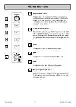
Page 9: ...roduces the classic Xone VCF sound by feeding some of the filter output back to its input The control ranges from mild producing a very subtle effect to wild producing a dramatic phase effect with feedback just short of oscillation 3 HPF Turns on the high pass bass cut filter slope 4 BPF Turns on the band pass bell shaped filter slope 5 LPF Turns on the low pass treble cut filter slope Frequency S...

Page 10: ... overrides just the left channel leav ing the program in the right channel The left monitor meter displays the Cue signal right displays program This is very useful when beat mixing using headphones 3 Cue Mix Control Allows the main mix output to be added to the Cue sig nal Turned fully anticlockwise only the active Cue is heard through the headphones when Cue is active Gradually turning clockwise...

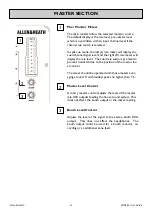
Page 11: ... cued mix audio is pre level to prevent mismatch due to the position of the master lev el control The mixer should be operated with these meters aver aging around 0 with loudest peaks no higher than 6 2 3 Master Level Control A rotary master control adjusts the level of the master mix XLR outputs feeding the house sound system This does not affect the booth output or the meter reading Booth Level ...

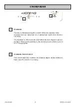
Page 12: ...sounds when scratch or cut mixing The crossfader is a VCA controller which affects the level of signals routed via the filters Make sure the switches on the channels you wish to fade are set to X or Y as appropriate CROSSFADER 2 1 Crossfader Curve Control This control adjusts the crossfader curve between dipped dipless and fast cut better suited for scratch or cut mixing 1 2 ...

Page 13: ...own or off before switching the console on or off This prevents any potential damage to speaker systems due to switch on transients CH 1 2 3 and 4 Phono Input Plug in turntables with magnetic cartridges requiring RIAA equalisation For non RIAA turn tables plug into the LINE input instead Do not plug in line level sources to the phono inputs as these will overload the preamp and cause severe high l...

Page 14: ... affected by the master fader or cue system X FX Send Return RCA phono Connect your external effects device and use the X FX dry wet control to send channel signals to the effects unit The signal returns to the mix bus but can be routed to the VCF filter by pressing the X FX button on the front panel filter section This allows the filter to be stacked with an external effects device Record Output ...

Page 15: ...Allen Heath 15 XONE 43 User Guide PANEL DRAWINGS Rear Panel Front Panel ...

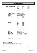
Page 16: ...eadroom Channels 20dB Frequency response 0 5dB 20Hz 20kHz Distortion 0 05 THD noise 1kHz Crosstalk 83dB inter channel Residual noise Mix 1 89dBu Booth 93dBu X FX 77dBu Rec 92dBu Mix noise Mix 1 82dBu Booth 84dBu X FX 77dBu Rec 87dBu Channel meters Peak reading 9 LED 20dB to 10dB Main meters Peak reading 9 LED 20dB to 10dB Mic EQ 2 Band 12dB Channel EQ 3 Band 6dB total kill Channel fader 45mm stere...

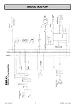
Page 17: ...Allen Heath 17 XONE 43 User Guide BLOCK DIAGRAM ...

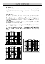
Page 18: ... lost when power is removed from the console The LPF is always selected when power is applied The graphs below show the effect on the audio frequency response for the three filter types The range of sweep from low to high frequency is shown together with the effect of adjusting RESONANCE one frequency with several resonance settings shown The vertical scale shows the amount of cut or boost around ...

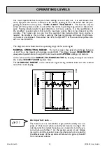
Page 19: ...Y of the sound that pleases the ear not the VOLUME OPERATING LEVELS The diagram below illustrates the operating range of the audio signal NORMAL OPERATING RANGE For normal music the signal should range between 6 and 6 on the meters with average around 0dB This allows enough HEADROOM for unexpected peaks before the signal hits its maximum CLIPPING voltage and distorts It also achieves the best SIGN...

Page 20: ...h you are less likely to experience problems Do not remove the earth connection from the console mains plug The console chassis is connected to mains earth through the power cable to ensure your safety Audio 0V is connected to the console chassis internally If problems are encountered with earth loops operate the audio ground lift switches on connected equipment accordingly or disconnect the cable...

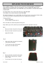
Page 21: ... are unsure of your ability to safely carry out this work then it is advised that you leave it to a qualified service technician Tools you will need T8 Torx screwdriver A small container to keep screws in Have a clean flat work surface ready before starting work Ensure that the power to the unit has been turned off and disconnected completely from the mains Step 1 Remove and retain 2 screws from f...

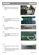
Page 22: ...The console base and front panel can now be separated Step 7 With care unplug the white harness from the connector PCB The cross fader and plate can now be sepa rated Step 8 Remove and retain 2 screws from crossfader plate Note that these 2 screws from the cross fad er plate are a different size length do not mix them up with the other screws Step 6 Remove the crossfader cap Remove and retain 2 sc...

Page 23: ...onal Innofader not supplied The standard crossfader must be fitted to slot 1 and not slot 2 Step 10 Screw the crossfader plate back to the con sole Replace the crossfader cap Connect the white harness from the connect or PCB Step 11 Re assembly of the console is the reverse of steps 1 5 When re assembling the console take great care to refit the wireform fully into the socket 1 2 ...

Reviews: