3-30
Malfunctions Not Indicated by a Fault
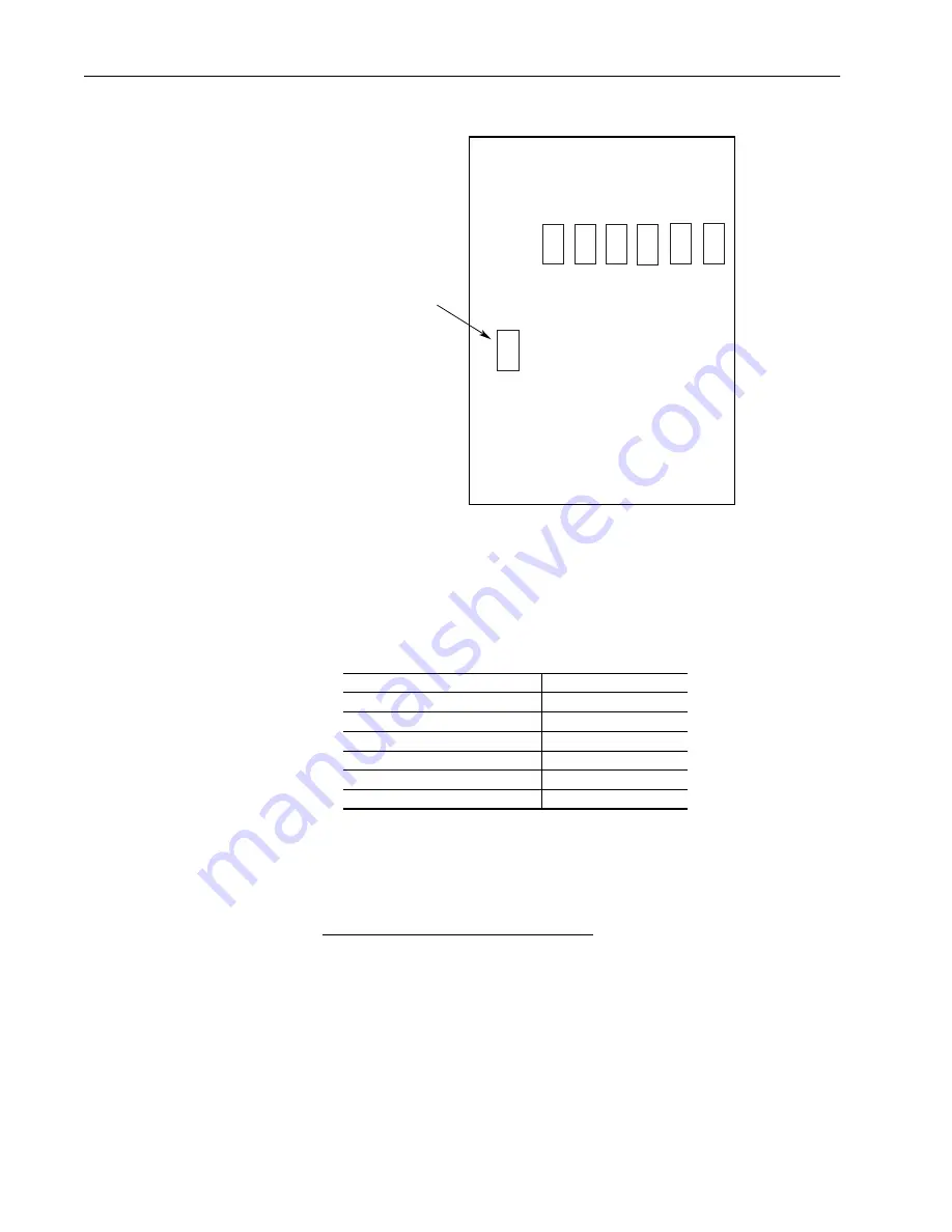
Figure 3.14 Series B SCR Layout
All resistances should be 100K ohm or greater. If a low resistance is
detected, remove the power board and determine which of the power
module pair is bad, replace it accordingly.
3.
Check the Gate to Cathode junction of each SCR module. With a DMM
on the 1K ohm scale, measure the resistance of each junction as follows:
All resistances should be between 7 to 30 ohms. If measurement is
outside of this range or one reading deviates significantly from the
majority, module replacement may be necessary.
Armature Pulse/Snubber Circuits (Series B)
The Armature Pulse/Snubber Circuits located on the power board provide
isolation of the gate firing circuit and also provide DV/DT protection for the
SCR modules. A malfunction of these devices will be evident in either an
overcurrent related fault, blown or tripped incoming protection devices or
erratic motor operation. Use the following procedure if a malfunction in this
circuitry is suspected.
1.
Disconnect and lock out all incoming voltage sources. To Gain Access to
the power board, swing down and remove PSI/Switcher Board.
From . . .
To . . .
PM1 – left SCR module G1 J15
A1 and G2 J16 to L1
PM2 – 2nd SCR module G1 J17
A2 and G2 J18 to L1
PM3 – 3rd SCR module G1 J19
A1 and G2 J20 to L2
PM4 – 4th SCR module G1 J21
A2 and G2 J22 to L2
PM5 – 5th SCR module G1 J23
A1 and G2 J24 to L3
PM6 – Right SCR module G1 J25
A2 and G2 J26 to L3
PM1 PM2 PM3 PM4
PM5
PM6
PM7
Armature SCR Modules
Field SCR Module
Aotewell Ltd industry-mall.net
www.aotewell.com
sales@aotewell.com
www.aotewell.com


