Rockwell Automation Publication 1718-UM001A-EN-E - December 2019
11
Product Specifications
Chapter 1
termination modules are installed in their reserved slots. These are
mechanically coded to avoid confusion.
Figure 5 - Overview of backplanes
Design and Dimensions
The following backplanes are operated as a base backplane and extension
backplane. Connect the two backplanes using the backplane cordset.
1718-A20
• Redundant configuration with slots for 2 gateways/adapters, 2 bus
termination modules, 2 power supplies
• Slots for max. 20 narrow or 10 wide I/O modules
• For PROFIBUS DP, MODBUS RTU, MODBUS TCP, Ethernet
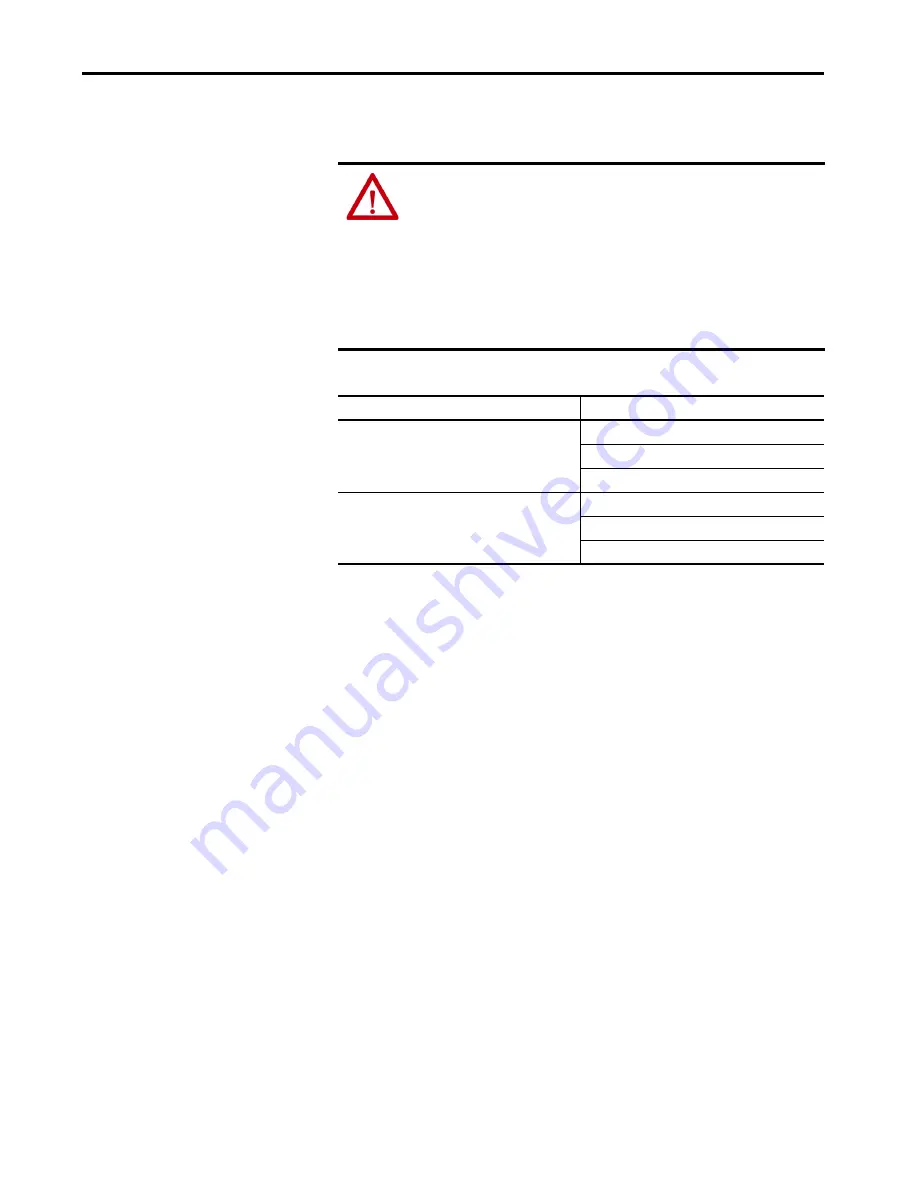
WARNING:
Risk of death as a result of using a damaged or tampered
backplane.
Using a defective or tampered backplane means that explosion protection can
no longer be guaranteed.
• Do not use a damaged backplane.
• The backplane must not be tampered with.
• In the event of a fault, the backplane must always be replaced with an
original backplane from Rockwell Automation.
Catalog Number
Description
1718-A20
Universal backplane
20 slots
Redundant: adapter and power supply
1718-A10
Universal backplane
10 slots
Redundant: adapter and power supply


