16
Rockwell Automation Publication 1718-UM001A-EN-E - December 2019
Chapter 1
Product Specifications
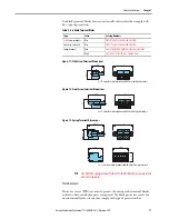
The two Ethernet interfaces on the front connect the device to the Ethernet
network.
Bus Termination Modules
Bus termination modules prevent the reflection of signals at the end of the bus
line. A bus termination module is required in each final unit of a bus line.
(Guess we dont have a ROK version of this module - add the figure if we do
support).
Power Supply Module
The power supplies provide power to all components of the remote I/O. The
slots for adapters are mechanically coded on the backplane and marked
accordingly.
(Provide product photo)
Placeholder Module
Placeholder modules keep non-wired field circuits in position. This module
has no electrical connection.
(Provide product photo)
Accessories
Field Wiring
The following accessories are available for field wiring.
Terminal Blocks
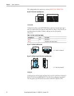
Terminal blocks are wired to the field devices, attached to the front sockets of
the I/O modules, and tightened using the side screws. Terminal blocks can
come in the form of screw terminals, front screw terminals, or spring terminals.
Use blue terminal blocks for intrinsically safe circuits.
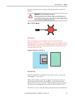
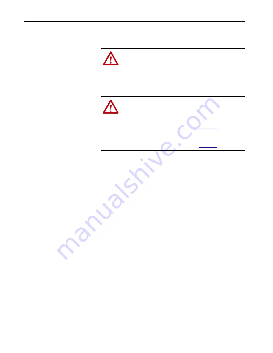
WARNING:
Explosion hazard in Zone 1.
When pulling out an M12 connector in Zone 1, a spark may form that ignites an
explosive mixture.
• Do not pull out M12 connectors in potentially explosive atmospheres.
• Use only original Fuchs cables.
(should we write this as cables from
the manufacturer Rockwell Automation?)
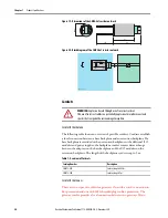
WARNING:
Property damage due to incorrect terminal assignment.
Incorrect terminal assignment and incorrectly positioned plug-in jumpers can
cause damage to the gateway.
• Ensure that the terminal assignment of the gateway is correct. Refer to the
backplane information in the Technical Data,
. Terminals 39 and
40 must be inserted when using the Ex-q gateway.
• Ensure that the plug-in jumper is correctly positioned. Refer to the
backplane information in the Technical Data,
.


