background image

Publication 1734-UM006A-EN-P - August 2000

Index

A

adding modules to the network


4-2

adding the communication device


4-2

assembly selection


3-8

B

base assembly, mounting


2-1

C

CE directives


P-2

checking I/O status


4-6

class instance attribute editor


5-2

class instance editor


5-1

configuration


4-1

configuration, default


1-8

counter mode


1-2

counter mode operation


1-2

D

data table - complete format


3-1

decimal position - frequency or counter display


3-6

default configuration


1-8

directives, European Union


P-2

E

encoder mode


1-2

encoder mode operation


1-3

F

format - data table


3-1

G

gate interval


3-6

gate interval setting


3-6

I

input word - present channel data


3-2

installation, module


2-2

installation, removable terminal block


2-4

K

keyswitch position


2-3

M

module installation


2-2

module/channel error bits


3-2

mounting base, removal


2-4

mounting, base assembly


2-1

N

new data indicator


1-8

O

operation - counter mode


1-2

operation - encoder mode


1-3

operation - rate measurement mode


1-7

operation - scalar


1-6

P

period rate mode - operation


1-5

period/rate mode


1-2

present channel data


3-2

preset configuration


3-7

R

rate measurement mode


1-2

rate measurement mode operation


1-7

rollover configuration


3-7

AB Drives

Summary of Contents for 1734-IJ

Page 1: ...Encoder Counter Modules 1734 IJ and 1734 IK User Manual AB Drives...

Page 2: ...lity is assumed by Rockwell Automation Inc with respect to use of information circuits equipment or software described in this manual Reproduction of the contents of this manual in whole or in part wi...

Page 3: ...Change Bars We marked with change bars as shown with this paragraph the areas in this manual that are different from previous editions and indicate the addition of new or revised information Chapter...

Page 4: ...Publication 1734 UM006B EN P August 2005 Summary of Changes 2 Notes...

Page 5: ...de 1 7 New Data Indicator 1 8 Default Configuration 1 8 Operating Mode Features 1 9 Operating Mode Features 1 9 Chapter 2 Install the Modules What This Chapter Contains 2 1 Before You Begin 2 1 Instal...

Page 6: ...Word 9 3 7 Safe State Values Configuration Word 10 3 8 Communicate Real Time Nonreal Time Information 3 8 Chapter 4 Configure Your Module What This Chapter Contains 4 1 Configuration Overview 4 1 Add...

Page 7: ...modules You must have the capability to download and use Electronic Data Sheet files We assume you know how to do this in this manual If you do not refer to your software user manuals or online help b...

Page 8: ...iceNet Communication Interface Installation Instructions 1734 PDN 1734 IN057 Field Potential Distributor Installation Instructions 1734 FPD 1734 IN059 POINT I O 24V dc Expansion Power Supply Installat...

Page 9: ...pulse to calculate an input frequency and verify it is above an error threshold This method does detect Lead Breakage since a broken wire will generate a 0Hz frequency Missing Pulse or Zero Frequency...

Page 10: ...Publication 1734 UM006B EN P August 2005 Preface 4 Operational Mode Zero Frequency Detection Input Monitored Counter No None Encoder No None Period Rate Yes Z Only Rate Measurement Y A Only...

Page 11: ...l base and the POINTBus containing the command information The main functional blocks are the the following Customer digital I O interface Counter ASIC Microprocessor The encoder counter module accept...

Page 12: ...s incoming pulses and returns a binary number 0 16 777 215max to the POINTBus The counter mode only accepts single phase inputs The module determines the Phase B input state and counts up or down acco...

Page 13: ...stem using a quadrature encoder may include an optional zero pulse or index serving as a reference mark for system reset The principal disadvantage of a system using incremental encoders is that a pow...

Page 14: ...ND trailing edges of A for a bidirectional count and channel B is used to determine the direction B leads A Count Down B follows A Count Up X4 Multiplying Encoder Mode Quadrature input signals are use...

Page 15: ...ode As the frequency of the incoming pulse train at the Z Gate Reset terminal increases the number of sampled pulses from the 5 MHz clock decreases Since accuracy is related to the number of pulses re...

Page 16: ...ed number There is one scalar value for each counter Acceptable values for the scalar are 1 2 4 8 16 32 64 and 128 The default value for each scalar is 1 Note that a 0 scalar is equivalent to a 1 The...

Page 17: ...ts Frequency is calculated by dividing the accumulated count by the user selected time period and is returned in the read data Allowable time periods are 10ms to 3s in 10ms increments with a default v...

Page 18: ...e mode The end of the programmed sample period in the Rate Measurement mode To use these bits reliably acquisition of data from the Counter Module must occur faster than the events which cause C1 C0 t...

Page 19: ...d stored in the Read Data file The counter continues counting The stored count is available in the Stored Accumulated Count word The stored count information remains until it is overwritten with new d...

Page 20: ...al is high Counting resumes from zero on the falling edge of the pulse at the Gate Reset terminal The stored count information will remain until it is overwritten with new data Store Reset Wait Start...

Page 21: ...2 6 Wire the Modules 2 7 Communicate with Your Module 2 9 ATTENTION Preventing Electrostatic Discharge This equipment is sensitive to electrostatic discharge which can cause internal damage and affect...

Page 22: ...nducted as well as radiated disturbance This equipment is supplied as open type equipment It must be mounted within an enclosure that is suitably designed for those specific environmental conditions t...

Page 23: ...ng side pieces engage the adjacent module or adapter ATTENTION POINT I O is grounded through the DIN rail to chassis ground Use zinc plated yellow chromated steel DIN rail to assure proper grounding T...

Page 24: ...l locking screw to a vertical position This releases the locking mechanism c Lift straight up to remove the mounting base d Repeat this procedure for the next mounting base assembly ATTENTION Do not d...

Page 25: ...rail locking screw is in the horizontal position You cannot insert the module if you unlock the locking mechanism 3 Insert the module straight down into the mounting base and press to secure WARNING W...

Page 26: ...wiring To reinsert the removable terminal block proceed as follows 1 Insert the RTB end opposite the handle into the base unit This end has a curved section that engages with the mounting base 2 Rota...

Page 27: ...cal position This releases the locking mechanism 6 Lift the mounting base straight up to remove Wire the Modules WARNING When you connect or disconnect the removable terminal block RTB with field side...

Page 28: ...hassis ground 7 Chassis ground 42016 Status of Input Z Input Aret Input Bret Input Zret Chassis Ground Input A Input B Input Z Chassis Ground Module Status Network Status of Input A Status of Input B...

Page 29: ...figuration is acceptable the counter ASIC is disabled while the ASIC is loaded with new operational parameters Outputs can turn off during this reconfiguration Message size Default Data Map Message si...

Page 30: ...t Counter Control Safe State 1 11 Set Get Requested Poll Produce Assembly 1 12 Set Get Requested Change of State Produce Assembly 1 Counter Configuration 07 06 05 04 03 02 01 00 ZI MD CF Counter 0 0 0...

Page 31: ...ered 0 B input not filtered 1 B input filtered 0 Z input not filtered 1 Z input filtered Scalar Selection 07 06 05 04 03 02 01 00 Scalar1 0 0 0 0 0 0 0 1 Z Fmin 0 149Hz 0 0 0 0 0 0 1 0 Z 2 Fmin 0 298H...

Page 32: ...0x65 Get Present Channel Data 4 Status 2 102 0x66 Get Stored Channel Data 4 Status 2 103 0x67 Get Present Channel Data 4 Stored Channel Data 4 Status 2 104 0x68 Get Programming Error Code 2 105 0x69 S...

Page 33: ...el Data 32 bit value of the stored accumulated count Status PE EF NR 0 0 0 0 0 0 ZS BS AS C1 C0 ZD 0 Programming Error Code PE 0 0 0 0 E10 E9 E8 E7 E6 E5 E4 E3 E2 E1 E0 Output Information Counter Cont...

Page 34: ...cified event ex rising edge of Z input In period rate 5 configurations it is the total accumulation of unscaled Z pulses for example if scaling is set to 128 after 128 Z pulses the accumulator will in...

Page 35: ...cted with the EEPROM during power up tests this bit is asserted to 1 It indicates that the content of the EEPROM has been corrupted most likely caused by loss of power during an executing write Not Re...

Page 36: ...lf cycles of Z In rate measurement 7 configuration pulses on the A input are counted over a sample interval specified by the time base The time it takes to determine a zero frequency in this configura...

Page 37: ...d Rate 0 1 1 0 Reserved 0 1 1 1 Rate Measurement 0 0 0 Store Count Disabled 0 0 1 Mode 1 store continue 0 1 0 Mode 2 store wait resume 0 1 1 Mode 3 store reset wait start 1 0 0 Mode 4 store reset star...

Page 38: ...128 Z 64 Z 32 and Z 16 should not be used when positioning is applied 0 is the default setting In the counter modes counter 0 x1 encoder 1 x2 encoder 2 x4 encoder 4 it attenuates the counter display...

Page 39: ...ence of 998 999 0 1 2 while incrementing or 2 1 0 999 998 while decrementing Rollover is a 32 bit number with a useable range of 1 value 0x01000000 16 777 216 In count 0 x1 encoder 1 x2 encoder 2 and...

Page 40: ...ed for a polled connection Assembly 102 is produced for a Change Of State COS connection Assemblies 103 104 and 106 are by Explicit message only Assembly 105 is consumed in a polled connection Data ma...

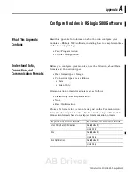
Page 41: ...ne This chapter shows configuration in the online mode Configuration dialogs appear similar in both modes The primary difference is that if you make changes offline you must go on line before the conf...

Page 42: ...n this case the communication device shown is a 1770 KFD 1 Click here to expand the list of communication adapters 2 Double click here to choose the scanner You can also click and drag the scanner nam...

Page 43: ...line or offline IMPORTANT If you commission a node on line you must power down your system before the change takes place 1 Go to the pulldown Tools Select Node Commissioning 2 Click on Browse 3 Select...

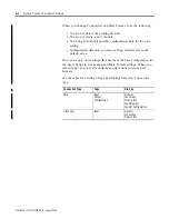
Page 44: ...tabs Each tab provides options view or edit Refer to the dialogs for an explanation of its features IMPORTANT This chapter shows configuration in the online mode Changes set in this mode take effect...

Page 45: ...rs IMPORTANT If configuration changes are made in offline mode they do not take effect until the system goes online Click on the Device parameters tab to get to the dialog for setting the parameters T...

Page 46: ...parameters as desired for your application When complete download to your module by clicking on the Download to Device button You can download each change as you make it using Single or download all...

Page 47: ...2005 Configure Your Module 4 7 Click on View File to view the actual EDS file Click on the EDS File tab to display the statistics of the EDS file used to configure this module You can view the actual...

Page 48: ...Publication 1734 UM006B EN P August 2005 4 8 Configure Your Module Notes...

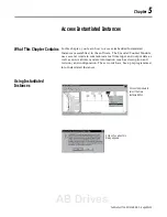
Page 49: ...he software The Encoder Counter Module uses several words to communicate real time input and output data as well as non real time module information such as description and revision and configuration...

Page 50: ...like this 1 Select the service code 3 Enter the class instance and attribute here 4 Click on Execute to initiate the action 3 Select the Receive Data size and radix 1 Type in the instance number here...

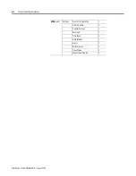
Page 51: ...ead the Present Channel Data assembly 10110 6516 can be requested Data is ordered as followed byte 0 is the least significant byte 8 bit byte Byte 0 16 bit word Byte 0 byte 1 32 bit long word Byte 0 b...

Page 52: ...August 2005 5 4 Access Instantiated Instances 106 0x6a Set Get Counter Configuration 1 Filter Selection 1 Decimal Position 1 Reserved 1 Time Base 2 Gate Interval 1 Scalar 1 Rollover Value 4 Preset Va...

Page 53: ...e these indicators for troubleshooting Indication Probable Cause Module Status Off No power applied to device Green Device is operating normally Flashing Green Device needs commissioning due to config...

Page 54: ...e established state Flashing Red One or more I O connections are in timed out state Red Critical link failure with failed communication device is present Device detected error that prevents it communi...

Page 55: ...llowing about Data formats and Connection types Data format type is Integer Connection types are as follows Data Listen Only Communication formats for adapters are as follows Listen Only Rack Optimiza...

Page 56: ...hat you cannot bring forward sets to the default value Once you apply new settings this becomes the base configuration for the next change in Connection and Data Format settings When you select Apply...

Page 57: ...e Connection dialog perform the following a Select a value for the Requested Packet Interval RPI entry Default value is 80 0 milliseconds Range is 2 0 to 750 0 milliseconds b Leave the following unche...

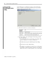
Page 58: ...one of the following Click another tab at the top of the dialog for example click Counter Configuration to continue configuration or Click OK which closes the Fault Program Action dialog or Click Can...

Page 59: ...e Counter Configuration mode Counter default Encoder X1 Encoder X2 or Encoder X4 Period Rate Rate Measurement 2 Refer to the table to see what entries to complete based on what you enter for Type Comp...

Page 60: ...fault is 16777215 Select a value greater than the value for Preset Preset 0 to 16777215 Default is 0 Select a value smaller than the value for Rollover Counter Attenuator 0 to 255 Default is 1 Select...

Page 61: ...which use the value you selected for Filter Filter A Filter B Filter Z 6 For Invert check the checkbox to invert the signal at Z input if you selected the following for Type Counter Encoder X1 Encode...

Page 62: ...ion 1 16 32 64 128 8 Perform one of the following Click another tab at the top of the dialog or Click OK which closes the dialog or Click Cancel to return to default values or Click Apply to save chan...

Page 63: ...P 2 E encoder mode 1 2 encoder mode operation 1 3 F format data table 3 1 G gate interval 3 6 gate interval setting 3 6 I input word present channel data 3 2 installation module 2 2 installation remov...

Page 64: ...on 1 6 setting counter parameters 4 4 setting rollover counts 3 7 setting safe state values 3 8 setting the counter gate interval 3 6 setting the preset value 3 7 stored accumulated channel data 3 2 V...

Page 65: ...ary information is provided 1 2 3 Can we add more information to help you procedure step illustration feature example guideline other explanation definition Technical Accuracy all provided information...

Page 66: ...EASE FOLD HERE NO POSTAGE NECESSARY IF MAILED IN THE UNITED STATES BUSINESS REPLY MAIL FIRST CLASS MAIL PERMIT NO 18235 CLEVELAND OH POSTAGE WILL BE PAID BY THE ADDRESSEE PLEASE FASTEN HERE DO NOT STA...

Page 67: ...AB Drives...

Page 68: ...Publication 1734 UM006B EN P August 2005 6 PN 957974 39 Supersedes Publication 1734 UM006A August 2000 2005 Rockwell International Corporation Printed in the U S A Back Cover...

Reviews: