Publication 1747-UM005B-EN-P - March 2006
Installation and System Configuration
4-11
RS-485
Connect Cable to the
DH-485 Port
The DH485 port can communicate to user devices through the
DH-485 Communication mode. Use a 1747-C11, 1747-C10, or
1747-C13 interface cable to connect the module to a link coupler
interfaced with the DH-485 network.
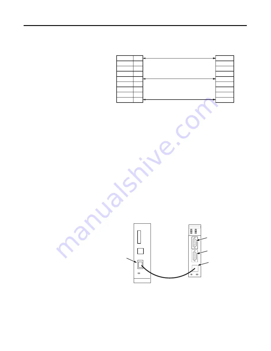
If you use the 1747-C11 or 1747-C10 cable, it connects between the
DH-485 port on the module and the J1 (CPU) connector on the link
coupler. Power for the link coupler will come from the interface
module.
Refer to page A-1 for more information.
Connect to the DH-485 Port via the 1747-C11 Cable
If you use the 1747-C13 cable, it connects between the DH-485 port
on the module and the J2 (Peripheral) connector on the link coupler.
Power for the link coupler must be provided from some other source.
See page A-1 for more information.
TRXD-
COM
TRXD+
1
2
3
4
5
6
7
8
9
TRXD-
COM
TRXD+
Peripheral
Interface Module
DTE
CONFIG Port
DF1 Port
DH-485 Port
J1 (CPU)
Cable
(1747-C11)
Link Coupler (1747-AIC)
Interface Module (1747-KE)
Summary of Contents for 1747-KE
Page 1: ...DH 485 RS 232C Interface Module Catalog Number 1747 KE User Manual AB Parts ...
Page 4: ...Publication 1747 UM005B EN P March 2006 2 Summary of Changes Notes ...
Page 12: ...Publication 1747 UM005B EN P March 2006 4 Preface ...
Page 26: ...Publication 1747 UM005B EN P March 2006 2 4 Quick Start ...
Page 88: ...Publication 1747 UM005B EN P March 2006 7 4 Interpret the LED Indicators ...
Page 116: ...Publication 1747 UM005B EN P March 2006 8 28 Application Examples ...
Page 120: ...Publication 1747 UM005B EN P March 2006 A 4 Specifications ...
Page 130: ...Publication 1747 UM005B EN P March 2006 C 6 Lithium Battery Replacement Handling and Disposal ...
Page 134: ...Publication 1747 UM005B EN P March 2006 D 4 Interface Module Configuration Worksheets ...
Page 138: ......


