Installation Instructions
Block I/O
Cat. No. 1791-0A32 Series B
10
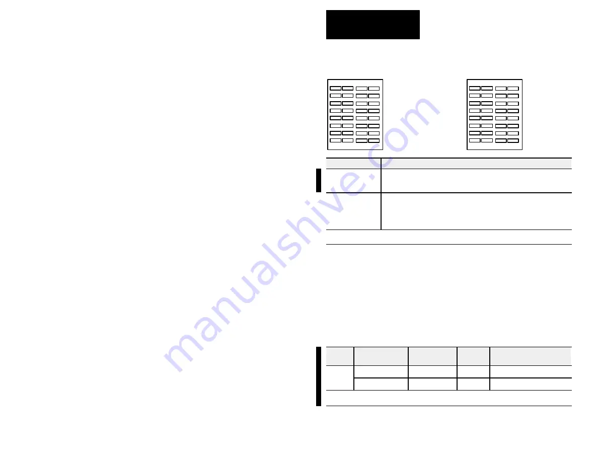
Indicators
OUT
OUT
00
01
02
03
04
05
06
07
10
11
12
13
14
15
16
17
COMM
STATUS
00
01
02
03
04
05
06
07
08
09
10
11
12
13
14
15
PLC
SLC
COMM
STATUS
00
01
02
03
04
05
06
07
10
11
12
13
14
15
16
17
00
01
02
03
04
05
06
07
08
09
10
11
12
13
14
15
G
G+1
OUT
OUT
G
G+1
Indicator
Description
COMM
OFF
ON
Flashing
Communication not established
Communication established
Processor in Program mode
STATUS
OFF
ON
Flashing
Normal
Error (hardware or software), block power low
COMM FAIL – communication cable disconnected, 100ms between valid frames, no
more than 255 valid frames between valid frames addressed to block, 20ms idle
time exceeded.
COMM and STATUS will alternately flash when processor restart lockout is selected, a fault has occurred and the processor
is communicating with the block.
Fusing
The block I/O module is internally fused to protect the module. No external
power fusing is required.
The outputs of the block I/O modules are not fused. Fusing of outputs is
recommended. If desired to fuse an output, you must provide external fusing.
Table D
Recommended Fuses
Type of
Circuit
Part Number
1
Size
Rating in
Amps
Maximum Surge Current
2
(repeatable every 2s)
ac
SAN-O SS2-1.0
0.25 in. x 1.25 in.
1.0A
3.0A for 50ms
ac
SAN-O MQ2-1.0
5mm x 20mm
1.0A
2.5A for 50ms
1
Note: Do not substitute another fuse for those listed.
2
The recommended fuses will withstand surges of the above listed currents for the time specified.
.


