


Rockwell Automation Publication 6177R-UM002E-EN-P - March 2017
25
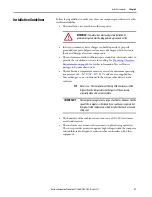
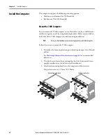
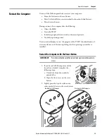
Install the Computer
Chapter 2
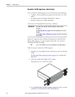
4. See
to decide which mounting holes to use on the bracket.
5. Drill holes in the wall or shelf to accommodate screws sized M6…M8.
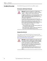
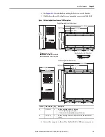
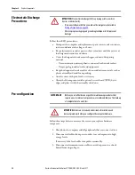
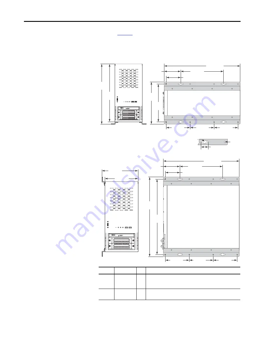
Figure 9 - Mounting Hole Locations on 750R Computers
6. Fasten the computer to the wall or shelf with M6…M8 mounting screws.
Bottom Mounting Bracket Hole Locations
Dimensions are in mm (in.).
IMPORTANT:
Bottom view is enlarged
for detail and not in scale to front view.
120 (4.73)
120 (4.73)
120 (4.73)
24 (0.95) x 4
382.1 (15.04)
60 (2.36)
240 (9.45)
210
(8.27)
194
(7.64)
70.5 (2.78)
375
(14.76)
360
(14.17)
A
B
Side Mounting Bracket Hole Locations
120 (4.73)
120 (4.73)
120 (4.73)
382.1 (15.04)
60 (2.36)
240 (9.45)
401.6
(15.81)
385.6
(15.18)
70.5 (2.78)
185 (7.28)
175 (6.89)
Mounting Hole Details (all brackets)
Callout
Dim, mm (in.) Qty
Description
A
Ø 10 (0.39)
4
Use these mounting holes for the following.
• You are replacing a legacy computer.
• Shock and vibration
are not
environmental elements.
B
Ø 6.5 (0.25)
8
Use these mounting holes when shock and vibration
are
environmental
elements.
Summary of Contents for 6177R-MM
Page 6: ...6 Rockwell Automation Publication 6177R UM002E EN P March 2017 Table of Contents Notes ...
Page 8: ...8 Rockwell Automation Publication 6177R UM002E EN P March 2017 Summary of Changes Notes ...
Page 101: ...Rockwell Automation Publication 6177R UM002E EN P March 2017 101 Index Notes ...
Page 102: ...102 Rockwell Automation Publication 6177R UM002E EN P March 2017 Index Notes ...
Page 103: ......


