background image

156

Rockwell Automation Publication 825-UM004D-EN-P - November 2012

Chapter 11

        Testing & Troubleshooting 

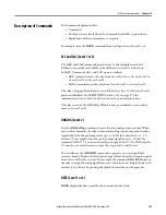
Contact Output Verification

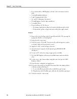
Disconnect the MCM converter module cable from the connector on the rear 
panel of the 825-P. Use the front panel MAIN > TARGETS > ROW 3 function 
to check that MCM/CWEFLT, Bit 0, is equal to one. Use MPS Explorer 
software to make TRIPC = 0 0 0 0 0 0 0 1 which closes the Trip contact.

Set AUX2C = 0 0 0 0 0 0 0 1. This will cause the AUX2 contact to close. Repeat 
the process for AUX3

AUX6, if present. Ensure that each contact closure 

produces the result that is needed in its associated annunciation, control, or trip 
circuit [remove control power to close the AUX1 (Alarm) contact].

Self-Tests

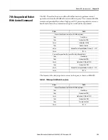
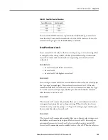
The 825-P runs a variety of self-tests. As shown in Table 89, when the relay 
detects certain self-test failures, the Critical Alarm Status is latched. A latched 
Critical Alarm Status closes the Trip contact and displays the associated message 
on the front panel.

When the Critical Alarm Status column in Table 89 shows Not Latched, the trip 
contact will not close because of the self-test failure. However, the associated 
message (if present) is displayed on the front panel.

All relay self-test failure messages are automatically sent to the serial port.

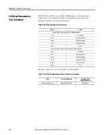
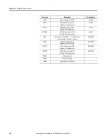
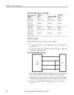
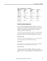
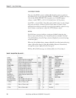
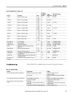
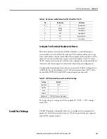
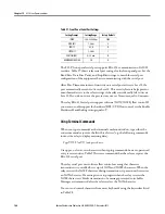
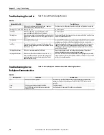
Table 89 - Relay Self-Tests  (Sheet 1 of 2)

Self-Test

Description

Limits

Protection 
Disabled on 
Failure

Critical 
Alarm Status

Front Panel Message 
on Failure

External RAM

Performs a read/write test on system RAM

Yes

Latched

External RAM FAILED

Internal RAM

Performs a read/write test on CPU RAM

Yes

Latched

Coldfire RAM FAILED

CR_RAM

Performs a checksum test on the active copy of settings Checksum

Yes

Latched

CR_RAM FAILED

Code Flash

Checksum is computed on code base

Checksum

Yes

Latched

PROGRAM MEMORY FAILED

Mainboard EEPROM

Checksum is computed on critical data

Checksum

Yes

Latched

EEPROM FAILED

Data Flash

Checksum is computed on critical data

Checksum

Yes

Latched

FLASH FAILED

Front Panel

Check if ID register matches expected

No

Not Latched

Voltage Board

Check if ID register matches part number

Yes

Latched

VT CALIBRATION FAILED

Current Board

Check if ID register matches part number

Yes

Latched

CT CALIBRATION FAILED

I/O Board

Check if ID register matches part number

Yes

Latched

I/O BOARD FAILURE

DeviceNet Board

DeviceNet card does not respond in 500 ms.

Yes

Latched

DEVICENET BOARD FAILURE

CPU Exception Vector

CPU error

Yes

Latched

Vector nn

Loss of MCU Crystal

Clock stopped

Yes

Latched

CLOCK STOPPED

Current Board A/D Offset

Measure DC offset at each input channel

50 mV

No

Not Latched

Voltage Board A/D Offset

Measure DC offset at each input channel

50 mV

No

Not Latched

+3.3V Warn

M3.3V power supply

<3.43V
>3.13V

No

Not Latched

+3.3V Fail

M3.3V power supply

<3.07V
>3.53V

Yes

Latched

+3.3V FAIL

+5V Warn

M5V power supply

<5.2V
>4.8V

No

Not Latched

Summary of Contents for 825-P

Page 1: ...Modular Protection System for Motors Catalog Number 825 P User Manual...

Page 2: ...nto consideration when applying products such as those described in this publication Reproduction of the contents of this copyrighted publication in whole or part without written permission of Rockwel...

Page 3: ...Contactors and Motor Starters EN 60947 5 1 Low Voltage Switchgear and Controlgear Part 5 Control Circuit Devices and Switching Elements Section 1 Electromechanical Control Circuit Devices This product...

Page 4: ...4 Rockwell Automation Publication 825 UM004D EN P November...

Page 5: ...r Connections 19 I O Diagram 20 AC Control Connection Diagrams 21 Fail Safe Non Fail Safe Tripping 21 Converter Module Connection 23 Core Balance Current Transformer Connections 24 Voltage Connections...

Page 6: ...g Statistics 54 SER Serialized Events Recording 55 STA Relay Status 55 SUM Events Summary Report 56 MET Instantaneous Metering RTD RTD Thermal Metering 57 TAR Display Target Words 58 Data Visualizatio...

Page 7: ...Factor 88 Frequency 89 Load Control Function 89 I O Configuration 90 Analog Output 90 Trip Inhibit Block 91 Output Relay Behavior 92 Timer Function 93 Front Panel Settings 93 Display Enable 94 I O Ass...

Page 8: ...Overview 131 Installation 131 Mounting 131 Wiring 132 Commissioning 134 Modbus Queries 135 Modbus Responses 135 Supported Modbus Function Codes 135 Modbus Exception Responses 136 Cyclical Redundancy...

Page 9: ...ure Your Terminal Emulation Software 163 Serial Port Settings 163 Using Terminal Commands 164 Serial Port Access Levels 165 Command Summary 166 Description of Commands 167 ACC and 2AC Level 1 or 2 167...

Page 10: ...bjects 242 Identity Object CLASS CODE 0x0001 243 Message Router CLASS CODE 0x0002 244 DeviceNet Object CLASS CODE 0x0003 244 Assembly Object CLASS CODE 0x0004 245 Custom Parameter Based Input Produced...

Page 11: ...ribes how to use MPS Explorer software to read diagnostic information and configure the 825 P Chapter 6 Configuring Protection Logic Functions Describes the operating characteristic of each protection...

Page 12: ...re by using MPS Explorer configuration and monitoring software a command line interface on a PC terminal emulation window such as Microsoft HyperTerminal the front panel menus and push buttons Example...

Page 13: ...nual to perform specific tasks A Quick Start Guide Publication 825 QS001 is also available It will help to step the first time user through the device commissioning process Features Standard Protectio...

Page 14: ...25 P are as follows Event summaries contain relay ID date and time trip cause and current voltage magnitudes Serialized Events Recording SER Motor running time since the last reset Start cycles since...

Page 15: ...ltraspec us Applications The 825 P can be used with the following across the line starter applications Low and medium voltage with 2 or 3 potential transformers With or without phase current transform...

Page 16: ...EN P November 2012 Chapter 1 Introduction Figure 1 AC Connections Without CTs 825 P 825 MCM L3 L2 L1 A1 1 3 5 6 4 2 A2 M 3 Converter Module Cat No 825 MCM2 Cat No 825 MCM5 Cat No 825 MCM20 Cat No 825...

Page 17: ...ity ratings for the relay The relay can be mounted indoors or in an outdoor extended enclosure where the relay is protected against exposure to direct sunlight precipitation and full wind pressure but...

Page 18: ...figured Ground Screw Voltage Input Card Expansion I O Incoming Power Communication Card Temperature Input Factory Configured Current Input MCM CWE DEVICENET RTD MODULE PTC RX CBCT S1 S2 BK BU SH WH RD...

Page 19: ...ns The power terminals are isolated from the chassis ground Use 16 AWG 1 5 mm2 size or heavier wire to connect to the POWER terminals Connection to external power must comply with IEC 947 1 and IEC 94...

Page 20: ...43 for mapping protection and or control elements to the Aux outputs Outputs Aux3 through Aux6 are available when an optional I O extension card is present Analog Output is available when an optional...

Page 21: ...osed N C terminal The terminals require different contact designations based on whether the Trip relay is configured for Fail Safe or Non Fail Safe operation The proper contact designations for Fail S...

Page 22: ...aligned with and not just to the single diagram that they are next to Figure 7 TRIP Contact Fail Safe and Non Fail Safe Options NOTE Contact numbering changes are based on TRIP Fail Safe setting Fail...

Page 23: ...gths greater than the 4 meter cable that is supplied MCM 4 M Connection Cable supplied with MCM d3 b b2 e2 e2 d2 a c1 c e d1 d b1 e3 Cat No 825 MCM2 825 MCM180 Cat No 825 MCM420 Cat No 825 MCM630N Dim...

Page 24: ...CBCT Ground Fault Sensor or customer supplied equivalent MCM CWE DEVICENET L1 L2 L3 N CBCT S1 S2 S1 S2 BK BU SH WH RD RTD MODULE RX PTC A1 A2 13 14 23 24 95 96 98 95 98 96 Y12 Y1 Y14 T1 T2 0 31 in 8 0...

Page 25: ...VT connected Figure 12 shows the three methods of connecting three phase voltages Figure 12 Voltage Connections The recommended fuse is the Bussman KTK 1 10 1 10 ampere Limitron fuse or its equivalent...

Page 26: ...at No 825 MCM630N T2 Core Balance Transformer Current ratio of core balance current transformer 1 2000 1 Output from core balance current transformer 0 500mA 825 P 825 MCM L3 L2 L1 T2 S1 S2 S 1 3 5 6...

Page 27: ...work as an alarm warning indicator it must be mapped to the Warning function bit S0 S1 K1 K1 A1 H1 H3 A2 TR AUX1 95 A1 13 825 P 96 98 A2 14 Contactor On push button Off push button Indicator Contactor...

Page 28: ...LA 2nd MOTOR FLA MOTOR LRC 2nd MOTOR LRC MOTOR LRT 2nd LOCKED ROTOR TIME ACCEL FACT 2nd ACCEL FACTOR RUN ST TC 2nd RUN STATE TIME K Figure 17 AC Connections for Full voltage Reversing Starter Star Del...

Page 29: ...pter 2 Figure 18 AC Connections for Star Delta Starting 825 P 825 MCM L3 L2 L1 1 3 5 1 3 5 1 3 5 6 4 2 6 4 2 6 4 2 W1 V1 U1 A1 A2 K1 A1 A2 K2D A1 A2 K3Y U1 Converter Module Cat No 825 MCM2 Cat No 825...

Page 30: ...Motor NOTE For AUX1 to work as an alarm warning indicator it must be mapped to the Warning function bit K1 S1 S0 H1 TR H3 AUX1 Contactor On push button Off push button Indicator Contactor closed Main...

Page 31: ...is lost or removed The battery is a 3V lithium coin cell Rayovac BR2335 or equivalent At room temperature 25 C the battery operates nominally for ten years at rated load When the relay is powered fro...

Page 32: ...into Slot A 8 Reinstall the relay rear panel and ground screw and then energize the relay Real Time Clock Battery Replacement To replace the real time clock battery do the following 1 De energize the...

Page 33: ...ID LINE 1 RID and UNIT ID LINE 2 TID settings described in Identifier Settings to change the contents of the information shown in Figure 23 If the front panel was in Access Level 2 it automatically r...

Page 34: ...failure Displays the type of latest failure see Chapter 11 Relay trip has occurred Displays the type or cause of the trip See the list of the types of Trip messages under the heading Front Panel Messa...

Page 35: ...e information that the relay measures and stores You can also use the front panel controls to view or modify relay settings All of the front panel functions are accessible using the seven button keypa...

Page 36: ...ist While editing a setting value decrease the value of the underlined digit LeftArrow Move the cursor to the left While viewing event data move to data for a newer event RightArrow Move the cursor to...

Page 37: ...are marked with the padlock symbol shown in Figure 25 Figure 25 Access Level Security Padlock Symbol Before you can perform a front panel menu activity that is marked with the padlock symbol you must...

Page 38: ...to other character rows 3 With the correct first character underlined press the Enter push button The first character appears in the upper line of the display and the blinking cursor moves one charact...

Page 39: ...e arrow push buttons to move the underline cursor to Del and press the Enter push button Clear Password To clear the entire password and start over use the arrow push buttons to move the underline cur...

Page 40: ...n PTC Rst RTD Settings RTD En RTD Rst RTD Loc RTD Type RTD Trip RTD Warn WdngTrip BearTrip TMPBias Freq Settings F1Trip Lvl F1Trip Dly F1WrnLvl F1Wrn Dly F2Trip Lvl F2Trip Dly F2WrnLvl F2Wrn Dly Load...

Page 41: ...Arrow buttons Press the Enter button to change a parameter setting Use the UpArrow and DownArrow and the LeftArrow and RightArrow push buttons to modify the parameter After changing the parameter pres...

Page 42: ...Show Status Reset TCU Set Show Menu RELAY PORT IO ASSIGN DATE TIME PASSWORD RELAY Menu Main Settings Overload Set Front Panel Set Display Enable Main Settings Menu UNIT ID LN 1 UNIT ID LN 2 PH ROTATI...

Page 43: ...FLAn Setting Combination Out of Range n 1 or 2 Main Settings Modify the CTRn or FLAn setting to satisfy 0 5 FLAn CTRn 2 5 when MCM2 is used 1 0 FLAn CTRn 5 0 when MCM5 is used 2 5 FLAn CTRn 20 when M...

Page 44: ...44 Rockwell Automation Publication825 UM004D EN P November 2012 Chapter 3 Front Panel Operation...

Page 45: ...rter Module Optional I O Module Optional Voltage Module and Optional Communication Module Connecting a Converter Module MCM Connect the MCM module to 825 P Apply power to the 825 P base relay The foll...

Page 46: ...on parameters reset the relay to the default parameters for the specific hardware configuration by navigating to Main Reboot Restore and select Restore Defaults in which the following display will app...

Page 47: ...the relay and remove the back cover Add the optional I O card into Slot D in the 825 P Replace the cover and reapply control power to the relay The 825 P will detect a hardware configuration change an...

Page 48: ...eplace the cover and reapply control power to the relay The 825 P will detect a hardware configuration change and display the following message Navigate to Main Status to view the Status display The d...

Page 49: ...m that you want this hardware change Select Yes to confirm the new hardware configuration and the display will show Press Enter to reboot the relay If there is an address conflict on the internal comm...

Page 50: ...will show the following message to indicate that something is different with the hardware configuration Navigate to Main Status to view the Status display The display will show the following message...

Page 51: ...be exported for analysis in other software such as Microsoft Excel Graphical output ranging from pilot lights to gauges and time plots can be modified for a specific application MPS Explorer software...

Page 52: ...ul connection has been established the software will display the device status by default To disconnect from the 825 P relay use the button or navigate to MPS Disconnect Disconnecting from the 825 P w...

Page 53: ...eters on the screen and will not be changed on the device until they are downloaded Button Summary MPS Explorer software incorporates a large number of functions displayed on the toolbar Table 6 Symbo...

Page 54: ...full analog output current for a defined period of time Enter the percentage and duration click the Test button and monitor the analog output for the expected current MOT Motor Operating Statistics Th...

Page 55: ...Physically clear the serialized events from the 825 P This cannot be recovered Export CSV Export the data in the list to a Comma Separated Value file STA Relay Status The Relay Status function displa...

Page 56: ...ber 2012 Chapter 5 Using MPS Explorer is able to confirm or ignore the changes from this screen The relay will reboot when the hardware changes are confirmed SUM Events Summary Report The Event Summar...

Page 57: ...plorer Chapter 5 MET Instantaneous Metering RTD RTD Thermal Metering The Instantaneous and Thermal Metering functions display the collection and export data in real time The user is able to configure...

Page 58: ...creen If data isbeing acquired viathe Start button itwillstop automatically when the window is hidden Export CSV Export the data in the list to a Comma Separated Value file csv for external analysis I...

Page 59: ...and forth without closing a window The user can display Current Average Magnitude Average Line Angle Imbalance Voltage Angle Imbalance Magnitude Frequency Ground Fault Current Core Balance Residual M...

Page 60: ...60 Rockwell Automation Publication825 UM004D EN P November 2012 Chapter 5 Using MPS Explorer both are highlighted use the arrow located in the middle to move the parameter to its assignment...

Page 61: ...to reduce space if metering for a long period of time NOTE The sampling time will be affected by the current serial port speed setting and other factors of latency involved in serial communications C...

Page 62: ...ign functions to the auxiliary relay and assign functions to the selected input When connected to the device the user can select I O Mapping from the Settings tree as shown Then a list of the Trip Aux...

Page 63: ...s notdetectthepresenceof thehardware evenwhentheauto detectoption is used Solution Ensure the correct serial port is selected in the Communications Settings window Make sure the serial cable is physic...

Page 64: ...64 Rockwell Automation Publication825 UM004D EN P November 2012 Chapter 5 Using MPS Explorer...

Page 65: ...825 P including the thermal element overcurrent elements load loss functions and load jam functions RTD Based Protection settings associated with the RTD inputs requires RTD Scanner Module Voltage Ba...

Page 66: ...l frequency Voltage transformer ratios and connections if used Type and location of resistance temperature devices RTDs if used Expected fault current magnitudes for motor or cable ground and three ph...

Page 67: ...hase current by 120 The thermal overload algorithm is dependent on the proper phase rotation setting An improper phase rotation will cause nuisance tripping Figure 28 Phase Rotation Setting Set the Ra...

Page 68: ...respectively If another MCM module is used the relay automatically sets CT Ratios 1 The CT ratio and full load current settings along with the connected MCM module configure the relay to accurately s...

Page 69: ...n phase to neutral PTs are connected to the relay set XFMR Connection equal to Wye Basic Motor Protection Setting Prompt Setting Range Factory Default PHASE VT RATIO 1 250 34 65 LINE VOLTAGE 100 30000...

Page 70: ...ee Figure 32 for selected settings of Thermal Overload curves The relay operates a thermal model with a trip value defined by the relay settings and a present heat estimate that varies with time and c...

Page 71: ...ess the specification states otherwise assume the time is the cold locked rotor time Multiply the cold locked rotor time by 0 833 to determine a hot locked rotor time which is acceptable for most moto...

Page 72: ...urrent 80 A Rated Locked Rotor Amps 480 A Safe Stall Time at 100 Volts Cold 18 seconds Hot 15 seconds Service Factor 1 2 Phase current transformers with 100 5 A rating and the MCM20 module are selecte...

Page 73: ...rt without tripping Set START INH LEVEL to a value equal to the incremental increase in percent thermal capacity utilized for one start plus additional margin The 825 P allows a new start when the per...

Page 74: ...to Off If the relay is connected to a device capable of interrupting fault current use the element to detect and trip for short circuit faults Set the Short Circuit Trip Level to a value greater than...

Page 75: ...hrough an external core balance zero sequence CT The residual RES elements operate using a residual ground fault measurement from the MCM module While the ground fault trip and warning levels offer an...

Page 76: ...25 P CBCT inputterminals as showninFigure 29 SettingthecorebalanceCT Ratioequalto 10 and Ground Fault Trip Level equal to 5 A with 0 10 second time delay ensures that the element quickly detects and t...

Page 77: ...et this delay to allow pumps or compressors to reach normal load Once armed this function issues a warning or trip if phase current drops below warn or trip level for the specified time delay Set the...

Page 78: ...balance where UB current imbalance percentage Im magnitude of phase current with largest deviation from average Iav magnitude of the average phase current FLA motor rated full load current In either c...

Page 79: ...load protection provided by the thermal model Figure 30 shows the typical current during motor start and the Start Motor Time setting Table 20 Protection Disable Settings Setting Prompt Setting Range...

Page 80: ...nge to delta regardless of the speed attained You can switch the maximum permissible time for star wye operation on or off If it is off the change to delta is made solely based on the motor current If...

Page 81: ...ates a trip signal and maintain it for at least this amount of time The relay does not issue a start during the Restart Block period The relay maintains the trip signal until enough time passes for th...

Page 82: ...ch trip Figure 31 shows typical currents during motor start normal and stall during start and the Speed Switch Trip Delay time setting Figure 31 Stalling During Starting Thermistor PTC Monitoring Tabl...

Page 83: ...not present If set to Man operator intervention e g front panel push button is required to reset the PTC trip Figure 32 Characteristic of PTC Sensors as per IEC 34 11 2 RTD Based Protection RTD Monit...

Page 84: ...s set the RTD Location equal to WDG For inputs connected to RTDs measuring bearing rise temperature set the RTD Location equal to BRG For the input connected to an RTD measuring ambient motor cooling...

Page 85: ...g Trip Voting is not enabled Bearing Trip Voting works similarly The warning and trip temperature settings for Bearing Ambient and Other RTD types function similarly except that trip voting is not ava...

Page 86: ...nable Thermal Model biasing the relay provides an RTD Bias Alarm when the RTD Thermal Capacity exceeds the thermal element Thermal Capacity by more than 10 percentage points while the winding temperat...

Page 87: ...opriate level for longer than the time delay setting the relay can issue a warning or trip signal The reactive power elements are disabled when the motor is stopped or starting Elements can be used to...

Page 88: ...el settings to Off Power Factor If the measured power factor falls below the leading or lagging level for longer than the time delay setting the relay can issue a warning or trip signal The power fact...

Page 89: ...age input option is present Otherwise the relay uses positive sequence current Load Control Function Table 33 Frequency Settings Setting Prompt Setting Range Factory Default FREQ1 TRIP LEVEL Off 55 0...

Page 90: ...parameters Use the Analog Output Select setting to select a parameter from the list of available options Table 36 shows description and scaling of the output for different parameter selections NOTE Pr...

Page 91: ...ng n 1 for Speed 1 or 2 for Speed 2 If the relay includes the voltage input option and you select PF parameter the analog output is scaled using power factor For power factors 0 8 lag unity and 0 8 le...

Page 92: ...re indicated on the relay chassis and also in Figure 4 When Trip Output Fail safe is enabled and the Trip contact is appropriately connected to the motor breaker or contactor the motor is automaticall...

Page 93: ...Front Panel Settings Table 39 Timer Settings Setting Prompt Setting Range Factory Default ON DELAY T1 0 240 s 0 OFF DELAY T1 0 240 s 0 ON DELAY T2 0 240 s 0 OFF DELAY T2 0 240 s 0 NOTE In addition to...

Page 94: ...minutes Use the front panel LCD Contrast setting to adjust the contrast of the liquid crystal display Display Enable The relay default front panel rotating display shows unit identifiers see Table 7...

Page 95: ...ing X PTC X Ground Fault Residual TRIP B X VAR X Underpower X Undervoltage X Overvoltage X Phase Reversal X Power Factor X Speed Switch X Ground Fault Core Balance TRIP C X Start Time X Frequency 1 X...

Page 96: ...R them together to drive the Trip output A logical OR describes when any one assigned element asserts the Trip relay will operate AuxiliaryI O Table 43 Aux Assignments Setting Prompt 0 1 2 3 4 5 6 7 D...

Page 97: ...RTD Winding Bearing Warning X Power Factor Warning X Ground Fault Core Balance Warning X Ground Fault Residual Warning Aux F X VAR Warning X Underpower Warning X Undervoltage Warning X Overvoltage War...

Page 98: ...t 4 in Aux D The user must reset the 825 P with the front Test Reset button or through communications to reset the auxiliary output If NETWORK is mapped to an AUX output the DeviceNet network can cont...

Page 99: ...ssignment you must connect a control contact to the input see Figure 16 for a typical connection diagram Table 45 Control Actions Function Control Action Emergency Start Overrides all active start inh...

Page 100: ...p reset command is received as follows an Auto Reset bit from Overload RTD or PTC protection elements asserts a rising edge of the Target Reset control bit from control input front panel serial port n...

Page 101: ...he above protection functions is not enabled by the relay settings that function does not affect trip unlatch Also note that the relay automatically asserts the trip signal if the motor stops and a lo...

Page 102: ...o Emergency Restart asserts the relay receives a network Emergency Restart control command When the Emergency Restart bit asserts the relay does the following Resets the motor thermal element capacity...

Page 103: ...rmal Overload Curves 100000 10000 1000 100 10 1 1 2 Multiples of Full Load Amps Trip Time in Seconds 3 4 5 6 7 8 9 10 600 400 200 100 50 25 10 5 Locked Rotor Time in seconds Trip times are for cold am...

Page 104: ...104 Rockwell Automation Publication825 UM004D EN P November 2012 Chapter 6 Configuring Protection Logic Functions...

Page 105: ...or monitoring and preventive maintenance purposes the 825 P provides a motor operating statistics report available using either the front panel the serial port or the optional network port Metering Th...

Page 106: ...L1 L2 and L3 IN Core Balance Ground Fault Current magnitudes A and phase angles IG Residual Ground Fault Current magnitude A and phase angle IM Average Current Magnitude Average Motor Load x Ie Curren...

Page 107: ...s convention are shown in Figure 35 Figure 35 Complex Power Measurement Conventions In the 825 P reported positive real power is always into the motor Table 48 RTD Input Status Messages Message Status...

Page 108: ...e protected motor The motor operating statistics include motor operating history such as time running time stopped percent time running of total time number of starts and number of emergency starts NO...

Page 109: ...the relay to save an event summary report and what the event summary data means The relay stores the five most recent event summary reports in nonvolatile memory These reports are numbered 1 through...

Page 110: ...te power up or settings change conditions Relay newly powered up or settings changed Each entry in the SER includes SER row number date time element name and element state Table 49 Event Report Curren...

Page 111: ...events that occurred before the beginning of the event summary report in Figure 36 The SER event report rows are explained in Table 50 numbered in correspondence to the Item column Figure 37 Example S...

Page 112: ...After a 10 second accelerating time the motor relay indicates the motor is running 9 Later the ambient temperature alarm element asserts 6 5 The ambient temperature trip element times out causing the...

Page 113: ...DeviceNet Communication Card is an optional accessory that enables connection of the 825 P Modular Protection System to the DeviceNet automation network The card occupies the communication expansion...

Page 114: ...ear DeviceNet plug Bus Status LED Status indicator for backplane communications Network Status LED Status indicator for DeviceNet communications Node Address Switch Rotary switch for setting the most...

Page 115: ...le from the back panel of the 825 P Modular Protection System as installed UCMM Unconnected Message Manager messages are supported with the ability to allocate up to 3 explicit message connections con...

Page 116: ...back panel 825 P Option Card installation instructions User Supplied Equipment Small slotted screwdriver 0 6 x 3 5 mm DeviceNet cable a thin cable with outside diameter of 6 9 mm 0 27 in is recommend...

Page 117: ...device on a DeviceNet network must have a unique node address which can be set to a value from 0 to 63 Keep in mind that most DeviceNet systems use address 0 for the master device Scanner and node add...

Page 118: ...re 41 Node Address and Data Rate Setting Switches Table 53 Node Address MAC ID Setting Switch Setting Description 0 63 Node address setting determined by switch values when set in this range MSD most...

Page 119: ...rface In this example a 1784 PCIDS module is chosen Other common DeviceNet interfaces are the 1770 KFD and 1784 PCD 3 Select OK 4 RSNetWorx notifies the user to upload or download devices before viewi...

Page 120: ...the device as an 825 P Modular Protection System skip ahead to the section Using the Node Commissioning Tool of RSNetWorx for DeviceNet RegisteringanEDSFile Download the 825 P DeviceNet EDS from the I...

Page 121: ...Commissioning Device Solution Window Explicit Messaging The 825 PDN is capable of using explicit messages to retrieve data that is not automatically acquired based on the input and output assembly of...

Page 122: ...the rest of the information can be defined In this example a tag was created with the name explicit_mess After the instruction has been named click on the gray box to define the rest of the instructi...

Page 123: ...me explicit_data Service Type Pull downmenuhasseveraloptions howeveronlytheGetAttributeSingleisusedforthis example TheClass Instance andAttributedefinetheactualinformationbeingrequested Additional con...

Page 124: ...gix program only runs if the logic has been enabled This can be done within the Logic Editor of RSNetWorx The operation configuration is accomplished by setting the Network Override and Communication...

Page 125: ...m the network or from the device hardware Hardware I O is the physical Inputs and Outputs located on the device such as push buttons and pilot lights that are connected to the 825 P Modular Protection...

Page 126: ...rid 9 From the toolbar select Discrete Input Point 10 From the pull down menu select Input 2 This is the remote Reset button that is based on the I O table example 11 Drag the input to the left of the...

Page 127: ...21 From the toolbar select Network Output Point 22 From the pull down menu select Flt Reset 23 Select OK 24 Moving your cursor into the grid place the Output to the right of the AND function block 25...

Page 128: ...m the pull down menu select Logic Verify 32 To toggle out of edit mode if you are online with a device select Tools 33 After selecting Edit from the main menu select Download from the pull down menu r...

Page 129: ...faults Net Inputs 1 Hdw Outputs Consumed IO Assy GrpA Pr FltValue Net Inputs 2 Trip Status 1 Produced IO Assy GrpA DN FltState Net Outputs Trip Status 2 Prod Assy Word 0 GrpA DN FltValue Network Overr...

Page 130: ...130 Rockwell Automation Publication825 UM004D EN P November 2012 Chapter 9 825 PDN DeviceNet Communication Card...

Page 131: ...single master device and multiple slave devices The communication is half duplex only one device transmits at a time The master transmits a binary command that includes the address of the desired slav...

Page 132: ...November 2012 Chapter 10 Modbus RTU Communications Wiring Table 61 RS 485 Connections top to bottom Pin Pin Function Definition 1 Dx Transmit Data Positive 2 Dx Transmit Data Negative 3 Rx Receive Da...

Page 133: ...ctions Figure 46 Example of wiring between a MicroLogix PLC Advanced Interface Converter AIC and the 825 PMB Modbus Option Card Pin Pin Function Definition 1 5V DC 2 RxD Receive Data 3 TxD Transmit Da...

Page 134: ...anel access uses the following path MAIN Set Show Port Port 4 Table 63 Modbus communication card settings The following table provides settings to use for each communication card Table 64 Communicatio...

Page 135: ...ice sends a response message after it performs the action requested in the query If the slave cannot execute the command for any reason it sends an error response Otherwise the slave device response i...

Page 136: ...ails and the message is ignored The devices use a similar process when the master sends queries 03h Read Holding Register Command Use function code 03h to read directly from the Modbus Register Map sh...

Page 137: ...ble 70 the command response is identical to the command request Bytes Field Requests from the master must have the following format 1 byte Slave Address 1 byte Function Code 03h 2 bytes Starting Regis...

Page 138: ...Preset Multiple Registers Command Bytes Field Requests from the master must have the following format 1 byte Slave Address 1 byte Function Code 06h 2 bytes Register Address 2 bytes Data 2 bytes CRC 16...

Page 139: ...er Increments Illegal register to set Illegal Data Address 02h Invalid Address Illegal Write Illegal number of registers toset Illegal Data Value 03h Illegal Write Incorrect number of bytes in query d...

Page 140: ...not saved in nonvolatile memory 4 RR Read only if running 1 when the setting is read only if in running operational state 5 P Power Cycle or Reset 1 when the setting change requires a power cycle or r...

Page 141: ...elow Table 79 61h Read Parameter Text Query Error Messages Error Error Code Returned Communication Counter Increments Illegal parameter to read Illegal Data Value 03h Illegal Register Bytes Field Requ...

Page 142: ...he query are shown below Table 81 61h Read Parameter Enumeration Text Query Error Messages Bytes Field Requests from the master must have the following format 1 byte Slave Address 1 byte Function Code...

Page 143: ...2 7Dh Encapsulated Packet Query Errors Bytes Field Requests from the master must have the following format 1 byte Slave Address 1 byte Function Code 7Dh 2 bytes Subfunction 2000h 1 byte Modbus Functio...

Page 144: ...access level has not been changed To enable modification of the settable parameters a valid Access Level E EAC password must be written to the password registers using function code 10h Note changing...

Page 145: ...f the Number of Records available is 25 write 11 to the Selected Starting Record to read records 11 20 Modbus Load Profile Register Operation To read load profile data from the 825 P using the Modbus...

Page 146: ...factor of 1000 divide by 1000 to obtain value 0x8000 LONG Value ranges 2147483647 2147483647 most significant word in lower address register 0x80000000 LONG10 LONG with scale factor of 10 divide by 10...

Page 147: ...correctly and accurately Commissioning tests must verify that the relay is properly connected to the motor and all auxiliary equipment Verify control signal inputs and outputs Use an AC connection che...

Page 148: ...relay trip contact 3 Verify the correct AC and DC connections by performing point to point continuity checks on the associated circuits 4 Apply AC or DC control voltage to the relay 5 After the relay...

Page 149: ...ly The expected magnitude is Applied Phase Current CTRN The expected phase angle is zero Figure 48 Three Phase Wye AC Connections NOTE If voltage transformers are used Apply the AC voltage signal to t...

Page 150: ...will cause the AUX2 contact to close c Repeat this process for AUX3 AUX6 if present Ensure that each contact closure produces the result required in its associated annunciation control or trip circuit...

Page 151: ...ta generated during commissioning testing from being confused with operational data collected later 24 Start the motor only when it is safe to do so 25 Verify the following AC quantities using the fro...

Page 152: ...CM2 0 5 2 5 A 825 MCM5 1 0 5 0 A 825 MCM20 2 5 20 A 825 MCM180 20 180 A 825 MCM420 160 420 A 825 MCM630N 160 630 A CurrentUnbalanceElementAccuracy 1 Connect the current source to the MCM module as sho...

Page 153: ...that Xfmt Connection Wye Figure 51 Wye Voltage Source Connections 3 Using the front panel SET SHOW or MPS Explorer software record the Phase CT Ratio Phase VT Ratio and Phase Rotation setting values 4...

Page 154: ...values 4 Apply the current and voltage quantities shown in Column 1 of Table 88 Values are given for Phase Rotation ABC and Phase Rotation ACB 5 Use the front panel METER or MPS Explorer software to...

Page 155: ...MPS Explorer software to verify that the relay self tests have not detected any WARN or FAIL conditions MeterVerification Verify that the relay is correctly measuring current and voltage if included b...

Page 156: ...Limits Protection Disabled on Failure Critical Alarm Status Front Panel Message on Failure External RAM Performs a read write test on system RAM Yes Latched External RAM FAILED Internal RAM Performs a...

Page 157: ...PERATURE WARN Temperature Fail Measure internal relay temperature 100 C Yes Latched TEMPERATURE FAIL Mainboard FPGA Fail if mainboard Field Programmable Gate Array does not accept program Yes Latched...

Page 158: ...e setup The relay serial port has received an XOFF halting communications Type Ctrl Q to send the relay XON and restart communications The relay does not respond to faults The relay is improperly set...

Page 159: ...at room temperature 25 C for ten years at rated load Experiences a low self discharge rate when the relay is powered from an external source Thus battery life can extend well beyond ten years The batt...

Page 160: ...ered it incapable of communicating on the network Duplicate MAC ID Bus off media issue Troubleshooting should be done to ensure that the network is correct terminators lengths etc and there is not a d...

Page 161: ...view self test status retrieve event summaries and obtain motor operating statistics reports Required Equipment To connect a PC serial port to the relay front panel serial port and enter relay command...

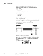
Page 162: ...dem communication cable with the pinout shown in Figure 53 For best performance the cable should not be more than 15 meters 50 feet long Figure 53 Serial Cable Pinout Figure 54 shows the front panel E...

Page 163: ...match the default settings shown in Table 96 For the best display use VT 100 terminal emulation If VT 100 is not available WYSE 100 and ANSI terminal emulations also work To change the port settings...

Page 164: ...you type commands at the terminal emulation window type either the entire command or just use the first three letters e g the following commands instruct the relay to display metering data Type METER...

Page 165: ...displays the prompt an equal sign This is referred to as Access Level 0 The only command available at Access Level 0 is the ACC command see Table 99 Type ACC at the Access Level 0 prompt and then pres...

Page 166: ...OG 2 Test analog output Page 167 DATE 1 2 View or Change date Page 167 METER 1 2 Display metering data Page 168 MOTOR 1 2 Display motor operating statistics report Page 170 MOTOR R or C 2 Reset motor...

Page 167: ...ormation on Access Level 1 and Access Level 2 password protection The relay sets the SALARM Relay Word bit for one second after a successful move to Access Level 2 ANALOG Level 2 Use the ANALOG p t co...

Page 168: ...vide access to the relay metering data The relay divides the displayed information into two groups Note All ASCII command responses in this section are examples only Your specific relay has difference...

Page 169: ...16 44 08 404 Prot System L1 L2 L3 Current Magnitude A 21 2 21 3 21 5 Current Angle deg 42 0 162 5 78 2 Average Current Magnitude A 21 3 Motor Load x Ie 0 9 GF Current Core Balance A 0 00 GF Current Co...

Page 170: ...Enter After entering the new password type PAS and then press Enter to inspect it If the password is correct record it for future reference If you make three incorrect password guesses access is deni...

Page 171: ...The date entries used with the SER command are dependent on the Date Format setting If the Date Format setting equals MDY then use the format mm dd yyyy for entered dates If the Date Format setting e...

Page 172: ...e it saves the new settings The SALARM Relay Word bit is set momentarily and the ENABLE LED extinguishes while the relay is disabled To change a specific setting enter the command shown in Table 103 T...

Page 173: ...en settings append an A to the SHOW command e g SHOW A n is M to enter I O mapping settings s is the short parameter name of the specific setting you want to jump to and begin setting If s is not ente...

Page 174: ...ESTAR_D N MAXSTART OFF TBSDLY OFF ABSDLY OFF E47T N SPDSDLYT OFF SPDSDLYA OFF EPTC N E49RTD Y RTDRST AUTO RTD1LOC WDG RTD1TY PT100 TRTMP1 150 ALTMP1 120 RTD2LOC OFF RTD3LOC WDG RTD3TY PT100 TRTMP3 OF...

Page 175: ...frontpanel FGPA programming unsuccessful or front panel FPGA failed OK WARN RAM Volatile memory integrity OK FAIL ROM Firmwareintegrity OK FAIL CR_RAM Integrity of settings in RAMand code that runs i...

Page 176: ...K OK Voltage VA VB VC Offset OK OK OK PS_Vdc FPGA GPSB HMI OK OK Ok Ok RAM ROM CR_RAM Non_Vol Clk_Bat Clock OK OK OK OK Ok OK PTC RTD MCM CWE Voltage I O_Crd Com_Crd OK Ok OK OK OK OK MAC_ID ASA DN_Ra...

Page 177: ...internal logic For more details refer to Chapter 6 Configuring Protection Logic Functions SUMMARY Level 1 or 2 The SUM n command displays a summary list in reverse chronological order of all the archi...

Page 178: ...er to specify the number of times 1 32767 to repeat the Relay Word row display If k is not specified the Relay Word row is displayed once See Table 106 for the definition of Row 0 See Table for a list...

Page 179: ...colons spaces commas or slashes For example set 22 47 36 by typing TIME 22 47 36 and then pressing Enter VieworChangeSettingswith Front Panel Serial Port View Settings Use the SHOW command to view rel...

Page 180: ...abled for as long as 5 seconds while it saves the new settings The ALARM Relay Word bit is set momentarily and the Enable LED extinguishes while the relay is disabled The relay also runs interdependen...

Page 181: ...enter front panel serial port settings n is M to enter I O mapping settings s is the name of the specific setting you want tojump to and begin setting If s isnot entered the relay starts at the first...

Page 182: ...182 Rockwell Automation Publication825 UM004D EN P November 2012 Chapter 12 ASCII Serial Communications...

Page 183: ...m cable Disk containing the firmware upgrade S19 file Upgrade Instructions The instructions below assume you have a working knowledge of your personal computer terminal emulation software In particula...

Page 184: ...e Y N Y Enter Are you sure Y N Y Enter Relay Disabled BAU 38400 Enter REC Enter Caution This command erases the relay s firmware If you erase the firmware new firmware must be loaded into the relay be...

Page 185: ...ollowing commands SET SET M and SET P h Set the relay passwords with the PAS command 10 Set the communications software settings baud rate number of data bits number of stop bits to agree with the por...

Page 186: ...186 Rockwell Automation Publication825 UM004D EN P November 2012 Chapter 13 Firmware Upgrade Instructions...

Page 187: ...Rated Continuous Thermal Current A 3 6 24 216 504 756 Rated Saturation Current 30 60 240 1350 3400 4600 Rated Frequency 50 60 Hz 3 Hz Voltage Input Option Card Rated Operating Voltage Ue 67 300VAC lin...

Page 188: ...Ithe 5 A Rated Operating CurrentIe 120V AC 240V AC 3 A 1 5 A Contact Rating Designation B300 Utilization Category AC15 Contact Reliability 5 mA 17V Mechanical Durability 10000 no load operations Picku...

Page 189: ...ply Voltage Us 110 240V AC Operating Range 0 80 1 2 Us Rated Frequency 50 60 Hz 5 Hz Max Power Consumption 5 VA Rated Insulation Voltage Ui 300V AC Rated Impulse Strength Uimp 4kV Pollution Degree 2 E...

Page 190: ...Radiated Class A Class A Conducted Phase Currents 2 Average Current 2 Average Motor Load 2 Current Imbalance 2 Ground Fault Current Residual 2 Ground Fault Current Core Balance 2 Frequency 0 1 Hz Lin...

Page 191: ...Power Consumption at Maximum Rated Current VA phase 0 1 0 2 0 4 Continuous Thermal Current A 3 6 24 Thermal Current 1 s Duration A 250 400 600 No Load An open circuit secondary is permitted as the bur...

Page 192: ...pical Power Consumption 2 04 W max 0 84 W typical Environmental Ambient Temperature Operating Storage 20 60 C 40 85 C 40 185 F Humidity operating 5 95 non condensing Vibration per IEC 68 2 6 5G Shock...

Page 193: ...lues provided include the following Value Function Setting Range Indicated as raw numerical values Scale Factor Indicate the decimal precision associated with each parameter This must be given close a...

Page 194: ...wer 0 10 Undervoltage 0 11 Overvoltage 0 12 Phase Reversal 0 13 Power Factor 0 14 Speed Switch 0 15 GF CoreBal 0 4 TRIP STATUS 2 0 Start Time 0 Get 1 Frequency 1 0 2 Frequency 2 0 3 RTD Other 0 4 RTD...

Page 195: ...nderpower 0 10 Undervoltage 0 11 Overvoltage 0 12 Reserved 0 13 Power Factor 0 14 Speed Switch 0 15 GF Core Bal 0 6 WARN STATUS 2 0 Reserved 0 Get 1 Frequency 1 0 2 Frequency 2 0 3 RTD Other 0 4 RTD A...

Page 196: ...ASSYWORD 0 0 447 1 Get Set 12 PROD ASSYWORD 1 0 447 3 Get Set 13 PROD ASSYWORD 2 0 447 4 Get Set 14 PROD ASSYWORD 3 0 447 5 Get Set 15 PROD ASSYWORD 4 0 447 6 Get Set 16 PROD ASSYWORD 5 0 447 7 Get S...

Page 197: ...8 AUX7 Status 0 9 AUX8 Status 0 10 AUX9 Status 0 11 AUX10 Status 0 23 FAULT1 COS MASK 0 Overload 0 Get Set 1 Undercurrent 0 2 Jam 0 3 Curr Imballance 0 4 Short Circuit 0 5 RTD Wind Bear 0 6 PTC 0 7 GF...

Page 198: ...t 0 5 RTD Wind Bear 0 6 PTC 0 7 GF Residual 0 8 VAR 0 9 Underpower 0 10 Undervoltage 0 11 Overvoltage 0 12 Phase Reversal 0 13 Power Factor 0 14 Speed Switch 0 15 GF CoreBal 0 26 WARN2 COS MASK 0 Star...

Page 199: ...FLTVALUE 0 Open 0 Get Set 1 Closed 36 GRPB DN FLTSTATE 0 Go to FltValue 37 0 Get Set 1 Ignore Trip 37 GRPB DN FLTVALUE 0 Open 0 Get Set 1 Closed 38 GRPB DN IDLSTATE 0 Go to FltValue 39 0 Get Set 1 Ign...

Page 200: ...N5 0 5 Net IN6 0 6 Net IN7 0 7 Net IN8 0 8 Net IN9 0 9 Net IN10 0 10 Net IN11 0 11 Net IN12 0 12 Net IN13 0 13 Net IN14 0 14 Net IN15 0 15 Net IN16 0 51 NETWORK INPUTS 17 32 0 Net IN17 0 Get 1 Net IN1...

Page 201: ...OUT14 0 14 Net OUT15 0 15 Net OUT16 0 53 NETWORK OVERIDE 0 Disabled 0 Get Set 1 Enabled 0 54 COMM OVERRIDE 0 Disabled 0 Get Set 1 Enabled 0 55 NET OUT COS MASK 0 Net OUT1 0 Get Set 1 Net OUT2 0 2 Net...

Page 202: ...4 40015 400015 OL RESET MODE 0 Manual 0 Get Set 1 Auto 115 40016 400016 OL RESET LEVEL 10 99 75 1 TCU Get Set 116 40017 400017 SERVICE FACTOR 101 150 101 100 Get Set 117 40018 400018 MOTOR LRC 25 120...

Page 203: ...et 1 Y 143 40044 400044 GF RES TRIP LEVL 10 100 50 100 x Ie Get Set 144 40045 400045 GF RES TRIP DLAY 0 500 0 100 s Get Set 145 40046 400046 GF RES WARN EN 0 N 0 Get Set 1 Y 146 40047 400047 GF RES WA...

Page 204: ...3 STARTS HR 0 Off 15 0 1 Get Set 173 40074 400074 MIN OFF TIME 0 Off 150 0 1 min Get Set Antibackspin 174 40075 400075 RESTART BLK TIME 0 Off 60 0 1 min Get Set Phase Rev Set 175 40076 400076 PH REV E...

Page 205: ...t 195 40096 400096 RTD4 TYPE 0 Pt100 1 Ni100 2 Ni120 3 Cu10 0 Get Set 196 40097 400097 RTD4 TRIP LEVEL 0 Off 250 0 1 C Get Set 197 40098 400098 RTD4 WARN LEVEL 0 Off 250 0 1 C Get Set 198 40099 400099...

Page 206: ...250 0 1 C Get Set 214 40115 400115 RTD9 LOCATION 0 Off 1 Wdg 2 Brg 3 Amb 4 Oth 0 Get Set 215 40116 400116 RTD9 TYPE 0 Pt100 1 Ni100 2 Ni120 3 Cu10 0 Get Set 216 40117 400117 RTD9 TRIP LEVEL 0 Off 250...

Page 207: ...2 40133 400133 TMP RTD BIASING 0 N 0 Get Set 1 Y Undervoltage Set 233 40134 400134 UV TRIP ENABLE 0 N 0 Get Set 1 Y 234 40135 400135 UV TRIP LEVEL 60 100 80 100 x Vnm Get Set 235 40136 400136 UV TRIP...

Page 208: ...40157 400157 UP TRIP LEVEL 1 2500 2500 1 kW Get Set 257 40158 400158 UP TRIP DELAY 0 240 0 1 s Get Set 258 40159 400159 UP WARN ENABLE 0 N 0 Get Set 1 Y 259 40160 400160 UP WARN LEVEL 1 2500 2500 1 kW...

Page 209: ...1 FREQ2 WARN ENABL 0 N 0 Get Set 1 Y 281 40182 400182 FREQ2 WARN LEVEL 450 650 600 10 Hz Get Set 282 40183 400183 FREQ2 WARN DELAY 0 2400 10 10 s Get Set Load Control Set 283 40184 400184 LOAD CONTROL...

Page 210: ...4 Aux4 Fail Safe 1 5 Aux5 Fail Safe 1 6 Aux6 Fail Safe 1 Timer Settings 295 40196 400196 ON DELAY T1 0 240 0 1 s Get Set 296 40197 400197 OFF DELAY T1 0 240 0 1 s Get Set 297 40198 400198 ON DELAY T2...

Page 211: ...ge 0 11 Overvoltage 0 12 Phase Reversal 0 13 Power Factor 0 14 Speed Switch 0 15 GF CB 1 303 40204 400204 TRIP ASSIGN HI 0 Start Time 0 Get Set 1 Frequency 1 0 2 Frequency 2 0 3 RTD Other 0 4 RTD Ambi...

Page 212: ...ge 0 11 Overvoltage 0 12 Phase Reversal 0 13 Power Factor 0 14 Speed Switch 0 15 GF CB 0 305 40206 400206 AUX1 ASSIGN REG2 0 Start Time 0 Get Set 1 Frequency 1 0 2 Frequency 2 0 3 RTD Other 0 4 RTD Am...

Page 213: ...11 Star 0 12 Delta 0 13 Start 0 14 Network 0 15 Reserved 0 307 40208 400208 AUX1 ASSIGN REG4 0 Overload Warn 0 Get Set 1 Undercurr Warn 0 2 Jam Warn 0 3 Curr Imbal Warn 0 4 RTD W B Warn 0 5 Pwr Facto...

Page 214: ...ge 0 11 Overvoltage 0 12 Phase Reversal 0 13 Power Factor 0 14 Speed Switch 0 15 GF CB 0 309 40210 400210 AUX2 ASSIGN REG2 0 Start Time 0 Get Set 1 Frequency 1 0 2 Frequency 2 0 3 RTD Other 0 4 RTD Am...

Page 215: ...11 Star 0 12 Delta 0 13 Start 0 14 Network 0 15 Reserved 0 311 40212 400212 AUX2 ASSIGN REG4 0 Overload Warn 0 Get Set 1 Undercurr Warn 0 2 Jam Warn 0 3 Curr Imbal Warn 0 4 RTD W B Warn 0 5 Pwr Facto...

Page 216: ...ge 0 11 Overvoltage 0 12 Phase Reversal 0 13 Power Factor 0 14 Speed Switch 0 15 GF CB 0 313 40214 400214 AUX3 ASSIGN REG2 0 Start Time 0 Get Set 1 Frequency 1 0 2 Frequency 2 0 3 RTD Other 0 4 RTD Am...

Page 217: ...11 Star 0 12 Delta 0 13 Start 0 14 Network 0 15 Reserved 0 315 40216 400216 AUX3 ASSIGN REG4 0 Overload Warn 0 Get Set 1 Undercurr Warn 0 2 Jam Warn 0 3 Curr Imbal Warn 0 4 RTD W B Warn 0 5 Pwr Facto...

Page 218: ...ge 0 11 Overvoltage 0 12 Phase Reversal 0 13 Power Factor 0 14 Speed Switch 0 15 GF CB 0 317 40218 400218 AUX4 ASSIGN REG2 0 Start Time 0 Get Set 1 Frequency 1 0 2 Frequency 2 0 3 RTD Other 0 4 RTD Am...

Page 219: ...11 Star 0 12 Delta 0 13 Start 0 14 Network 0 15 Reserved 0 319 40220 400220 AUX4 ASSIGN REG4 0 Overload Warn 0 Get Set 1 Undercurr Warn 0 2 Jam Warn 0 3 Curr Imbal Warn 0 4 RTD W B Warn 0 5 Pwr Facto...

Page 220: ...ge 0 11 Overvoltage 0 12 Phase Reversal 0 13 Power Factor 0 14 Speed Switch 0 15 GF CB 0 321 40222 400222 AUX5 ASSIGN REG2 0 Start Time 0 Get Set 1 Frequency 1 0 2 Frequency 2 0 3 RTD Other 0 4 RTD Am...

Page 221: ...11 Star 0 12 Delta 0 13 Start 0 14 Network 0 15 Reserved 0 323 40224 400224 AUX5 ASSIGN REG4 0 Overload Warn 0 Get Set 1 Undercurr Warn 0 2 Jam Warn 0 3 Curr Imbal Warn 0 4 RTD W B Warn 0 5 Pwr Facto...

Page 222: ...ge 0 11 Overvoltage 0 12 Phase Reversal 0 13 Power Factor 0 14 Speed Switch 0 15 GF CB 0 325 40226 400226 AUX6 ASSIGN REG2 0 Start Time 0 Get Set 1 Frequency 1 0 2 Frequency 2 0 3 RTD Other 0 4 RTD Am...

Page 223: ...11 Star 0 12 Delta 0 13 Start 0 14 Network 0 15 Reserved 0 327 40228 400228 AUX6 ASSIGN REG4 0 Overload Warn 0 Get Set 1 Undercurr Warn 0 2 Jam Warn 0 3 Curr Imbal Warn 0 4 RTD W B Warn 0 5 Pwr Facto...

Page 224: ...Trip 0 10 Reserved 0 11 Reserved 0 12 Reserved 0 13 Reserved 0 14 Reserved 0 15 Reserved 0 329 40230 400230 IN2 ASSIGN 0 Emergency Start 0 Get Set 1 Disable Settings 0 2 Trip Reset 0 3 Timer 1 0 4 Ti...

Page 225: ...Trip 0 10 Reserved 0 11 Reserved 0 12 Reserved 0 13 Reserved 0 14 Reserved 0 15 Reserved 0 331 40232 400232 IN4 ASSIGN 0 Emergency Start 0 Get Set 1 Disable Settings 0 2 Trip Reset 0 3 Timer 1 0 4 Ti...

Page 226: ...4 40235 400235 RESET TRIP 0 Ready 0 Get Set 1 Reset 335 40236 400236 SET TO DEFAULTS 0 Ready 0 Get Set 1 Reset 336 40237 400237 RESET STAT DATA 0 Ready 0 Get Set 1 Reset 337 40238 400238 RESET HIS DAT...

Page 227: ...VAB ANGLE 1800 1800 10 Get 359 40260 VBC 0 65535 1 V Get 360 40261 VBC ANGLE 1800 1800 10 Get 361 40262 VCA 0 65535 1 V Get 362 40263 VCA ANGLE 1800 1800 10 Get 363 40264 AVERAGE LINE 0 65535 1 V Get...

Page 228: ...40288 RTD5 32768 32767 1 C Get 388 40289 RTD6 32768 32767 1 C Get 389 40290 RTD7 32768 32767 1 C Get 390 40291 RTD8 32768 32767 1 C Get 391 40292 RTD9 32768 32767 1 C Get 392 40293 RTD10 32768 32767...

Page 229: ...59 1 Get 408 40309 STOPPED TIME hh 0 23 1 Get 409 40310 STOPPED TIME dd 0 65535 1 Get 410 40311 TIME RUNNING 0 1000 10 Get 411 40312 STARTS COUNT 0 65535 1 Get 412 40313 EMER START COUNT 0 65535 1 Ge...

Page 230: ...rip Get 1 Overload Trip 2 Lockd RotorTrip 3 UndercurrTrip 4 Jam Trip 5 Curr Imbal Trip 6 Short Ckt Trip 7 Ground Flt Trip 8 Speed Sw Trip 9 Undervolt Trip 10 Overvolt Trip 11 Underpower Trip 12 Pwr Fa...

Page 231: ...65535 1 V Get 436 40337 EVENT DELTA WYE 0 Delta Get 1 Wye 437 40338 RESERVED 438 40339 RESERVED 439 40340 RESERVED 440 40341 RESERVED 441 40342 RESERVED 442 40343 RESERVED 443 40344 RESERVED Trip War...

Page 232: ...ote Trip 11 Comm Fault 12 Alarm Critical 13 Reserved 14 Reserved 15 Reserved 446 40347 WARN STATUS LO 0 Overload Warn Get 1 Undercurr Warn 2 Jam Warn 3 Curr Imbal Warn 4 Short Ckt Warn 5 RTD W B Warn...

Page 233: ...1 Freq1 Warn 2 Freq2 Warn 3 RTD Other Warn 4 RTD Amb Warn 5 PTC Error Warn 6 RTD Error Warn 7 MCM CWE Err Warn 8 Comm Idle Warn 9 Comm Loss Warn 10 Reserved 11 Comm Fault Warn 12 Alarm Warn 13 Reserv...

Page 234: ...234 Rockwell Automation Publication 825 UM004D EN P April 2012 Chapter B ParameterList...

Page 235: ...of Relay Status bits and their descriptions The Relay Word bit row numbers correspond to the row numbers used in the TAR command in MPS Explorer Software For access from the front panel use the follow...

Page 236: ...eutral Core Balance Overcurrent 3 SMTRIP 7 Asserts when Start Motor Timer times out 81D1T 6 Definite Time Over and Underfrequency Element Trip Level 1 Assert when the frequency has been either above o...

Page 237: ...ther Temperature Alarm Asserts when any healthy Other RTD temperature exceeds its alarm warning set point 7 AMBALRM 7 Ambient Temperature Alarm Asserts if the healthy ambient RTD temperature exceeds i...

Page 238: ...X3 AUX6 are optional 0 Reserved for future use Table 112 Relay Word Bit Definitions for the 825 P Sheet 4 of 4 Row Bit Definition Table 113 Additional 825 P Relay Status Bits for SER Command Bit Name...

Page 239: ...1 2 Display thermal and RTD metering data MOT 1 2 Display motor operating statistics report MOT R or C 2 Reset motor operating statistics PAS 2 Show existing Access Level 1 and Level 2 passwords PAS...

Page 240: ...art motor SUM 1 2 View event summary reports SUM R or C 1 2 Reset event summary buffer TAR 1 2 Display Relay Word Row 0 front panel target LEDs TAR nk 1 2 Display Relay Word Row n n 0 10 Repeat k time...

Page 241: ...t Produced Assemblies 247 Standard Output Consumed Assemblies 250 Connection Object CLASS CODE 0x0005 251 Discrete Input Point Object CLASS CODE 0x0008 254 Discrete Output Point Object CLASS CODE 0x00...

Page 242: ...by some configuration tools since all of the information necessary for an EDS file can be extracted from the 825 P Modular Protection System Product Codes Configuration tools use product codes to ide...

Page 243: ...t Device Type UINT 3 3 Get Produce Code UINT 100 64 hex 4 Get Revision Major Revision Minor Revision Structure of UINT UINT 0RRRMMMM 0 reserved by DeviceNet RRR Revision of Motor Relay MMMM Revision o...

Page 244: ...lowing instance attributes are supported Allocation_byte Bit 0 Explicit messaging Bit 1 Polled I O Bit 4 COS I O Bit 5 Cyclic I O Bit 6 Acknowledge Suppression The following services are implemented f...

Page 245: ...e _Connection_Set Attribute ID Access Rule Name Data Type Value 2 Get Max Instance UINT 189 Instance Type Description 2 Consumed Required ODVA Consumed Instance 50 Produced Required ODVA Produced Inst...

Page 246: ...e parameterpointed to by Produced Word 2 Param low byte 5 Value of the parameterpointed to by Produced Word 2 Param high byte 3 6 Value of the parameterpointed to by Produced Word 3 Param low byte 7 V...

Page 247: ...put produced assembly Instance 50 ODVA Overload Byte Bit 7 Bit 6 Bit 5 Bit 4 Bit 3 Bit 2 Bit 1 Bit 0 0 Fault Instance 51 ODVA Starter Byte Bit 7 Bit 6 Bit 5 Bit 4 Bit 3 Bit 2 Bit 1 Bit 0 0 Warning Fau...

Page 248: ...5 Phase Current Byte Bit 7 Bit 6 Bit 5 Bit 4 Bit 3 Bit 2 Bit 1 Bit 0 0 Warning Tripped 1 Thermal Capacity Used 2 Average 3 Phase Current low 3 Average 3 Phase Current high 4 Asymmetry 5 Max value of a...

Page 249: ...186 Trip Status 2 Byte Bit 7 Bit 6 Bit 5 Bit 4 Bit 3 Bit 2 Bit 1 Bit 0 0 MCM err RTD err PTC err RTD Amb RTD other Freq 2 Freq 1 Stall 1 Remote Comm Idle Comm Loss Instance 187 Warning Status 1 Byte...

Page 250: ...4 Bit 3 Bit 2 Bit 1 Bit 0 0 Aux 8 Aux 7 Aux 6 Aux 5 Aux 4 Aux 3 Aux 2 Aux 1 1 Flt Reset Aux 10 Aux 9 Instance 151 Standard Consumed Starter with Network Inputs Byte Bit 7 Bit 6 Bit 5 Bit 4 Bit 3 Bit 2...

Page 251: ...Net Input 13 Net Input 12 Net Input 11 Net Input 10 Net Input 9 Instance 183 Consumed Network Inputs 17 32 Byte Bit 7 Bit 6 Bit 5 Bit 4 Bit 3 Bit 2 Bit 1 Bit 0 0 Net Input 24 Net Input 23 Net Input 2...

Page 252: ...Get Transport Class Trigger USINT 0x82 Server Transport Class 2 If alloc_choice polled and acksuppressionisenabledthen value 0x80 4 Get Produced Connection ID UINT 01111xxxxxx xxxxxx node address 5 Ge...

Page 253: ...COS unacknowledged 0x13 COS acknowledged 4 Get Produced Connection ID UINT 01101xxxxxx xxxxxx node address 5 Get Consumed Connection ID UINT 10xxxxxx101 xxxxxx node address 6 Get Initial Comm Charact...

Page 254: ...83 Server Transport Class 3 4 Get Produced Connection ID UINT Depends on message group and Message ID 5 Get Consumed Connection ID UINT Depends on message group and Message ID 6 Get Initial Comm Chara...

Page 255: ...te Output Point Object Attribute ID Access Rule Name Data Type Value 3 Get Value BOOL 0 OFF 1 ON 115 Get Set Force Enable BOOL 0 Disable 1 Enable 116 Get Set Force Value BOOL 0 OFF 1 ON Service Code I...

Page 256: ...lar Protection System User Manual publication 825 UM004 for instructions on assignment of functions to the auxiliary output relays An output that is not used in a DeviceLogix program follows the rules...

Page 257: ...y parameters Refer to AppendixB of the 825 P Modular Protection System User Manual publication 825 UM004 for details of the individual motor relay parameter instances The following services are implem...

Page 258: ...1 Get Set Value Specified in Descriptor 2 Get Link Path Size USINT 3 Get Link Path Array of BYTE EPATH 4 Get Descriptor WORD 5 Get Data Type EPATH 6 Get Data Size USINT 7 Get Parameter Name String SHO...

Page 259: ...below Instance 1 contains the following attributes Instance 2 contains the following attributes Attribute ID Access Rule Name Data Type Value 1 Get Group Name String SHORT_STRING 2 Get Number of Membe...

Page 260: ...FF 1 ON Attribute ID Access Rule Name Data Type Value 3 Get Number of Instances USINT 4 4 Get Binding Array of UINT 3 4 5 6 7 Get Set Fault Action BOOL 0 Fault Value attribute 1 Hold Last State 8 Get...

Page 261: ...owledge Handler Object is supported The following instance attributes are supported The following common services are implemented for the Acknowledge Handler Object Service Code Implemented for Servic...

Page 262: ...f the DeviceNet Interface Object is supported Service Code Implemented for Service Name Class Instance 0x0E No Yes Get_Attribute_Single 0x10 No Yes Set_Attribute_Single Attribute ID Access Rule Name D...

Page 263: ...Set Set To Defaults BOOL 0 1 0 0 No action 1 Reset 23 Get I O Produced Size USINT 0 16 Read only 24 Get I O Consumed Size USINT 0 8 Read only 30 Get DeviceNet Voltage UINT Read only 50 Get Set PNB COS...

Page 264: ...P April 2012 Chapter E DeviceNet Information The following common services are implemented for the DeviceNet Interface Object Service Code Implemented for Service Name Class Instance 0x0E No Yes Get_...

Page 265: ......
Page 266: ...problem within the first 24 hours of installation review the information that is contained in this manual You can contact Customer Support for initial help in getting your product up and running New...

Reviews: