Rockwell Automation Publication 825-UM004D-EN-P - November 2012
93
Configuring Protection & Logic Functions
Chapter
6
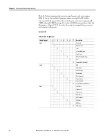
Timer Function
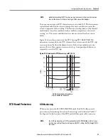
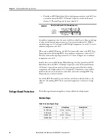
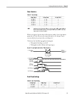
When you assign an input contact and an output auxiliary relay to appropriate
parameters of Timer Function, the output responds to the change in input
contact with the characteristics shown in Figure 33.
This feature has the following application examples:
•
Time-graded switching on and off
•
Delaying the transfer of alarm and trip messages
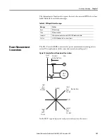
Figure 33 - Operating Characteristics of Timer Functions
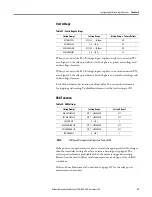
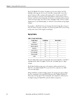
Front Panel Settings
Table 39 - Timer Settings
Setting Prompt
Setting Range
Factory Default
ON DELAY T1
0…240 s
0
OFF DELAY T1
0…240 s
0
ON DELAY T2
0…240 s
0
OFF DELAY T2
0…240 s
0
NOTE:
In addition to setting the On and Off Delays, you must assign TIMER1 and/or TIMER2 to a
control input (see Table 44). You must also assign TIMER1T and/or TIMER2T to auxiliary
output relays. See Table 43 for detail.
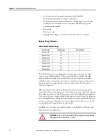
Table 40 - Front Panel Settings
Setting Prompt
Setting Range
Factory Default
LCD TIMEOUT
Off, 1…30 min
15
LCD CONTRAST
1…8
5
T on
T off
T off
T on
T off
Output
Relay Word
TIMER nT
Control Input
TIMER
Control Input
On-Delay
(T off = 0)
Off-Delay
(T on = 0)
On-Off-Delay
On-Off-Delay
T on
T on = On-delay
T off = Off-delay
n = 1 or 2
T on
T off
Summary of Contents for 825-P
Page 1: ...Modular Protection System for Motors Catalog Number 825 P User Manual...
Page 4: ...4 Rockwell Automation Publication 825 UM004D EN P November...
Page 64: ...64 Rockwell Automation Publication825 UM004D EN P November 2012 Chapter 5 Using MPS Explorer...
Page 234: ...234 Rockwell Automation Publication 825 UM004D EN P April 2012 Chapter B ParameterList...
Page 265: ......


