


Rockwell Automation Publication 825-UM004D-EN-P - November 2012
117
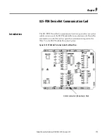
825-PDN DeviceNet Communication Card
Chapter
9
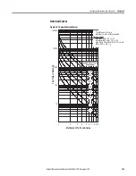
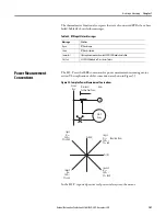
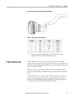
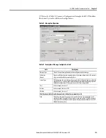
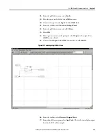
Figure 40 - Connecting 5-Pin Linear Plug to DeviceNet Cable
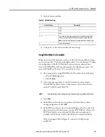
Table 52 - Linear Plug Function Descriptions
5.
Connect the wired 5-pin linear plug to the 825-PDN DeviceNet
Communication Card, securing with the two screws
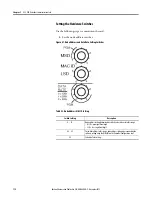
Node Commissioning
The 825-PDN DeviceNet Communication Card is shipped with a default
software node address (MAC ID) setting of 63 and the data rate set to Autobaud.
Each device on a DeviceNet network must have a unique node address which can
be set to a value from 0 to 63.
Keep in mind that most DeviceNet systems use address 0 for the master device
(Scanner) and node address 63 should be left vacant for introduction of new slave
devices.
The node address and data rate for the 825-PDN DeviceNet Communication
Card can be changed using software or by setting the hardware switches that
reside on the card. While both methods yield the same result, it is a good practice
to choose one method and deploy it throughout the system.
Terminal
Color
Signal
Function
5
Red
V+
Power Supply
4
White
Can_H
Signal High
3
Bare
SHIELD
Shield
2
Blue
CAN_L
Signal Low
1
Black
V-
Common
Summary of Contents for 825-P
Page 1: ...Modular Protection System for Motors Catalog Number 825 P User Manual...
Page 4: ...4 Rockwell Automation Publication 825 UM004D EN P November...
Page 64: ...64 Rockwell Automation Publication825 UM004D EN P November 2012 Chapter 5 Using MPS Explorer...
Page 234: ...234 Rockwell Automation Publication 825 UM004D EN P April 2012 Chapter B ParameterList...
Page 265: ......