


Rockwell Automation Publication 825-UM004D-EN-P - November 2012
35
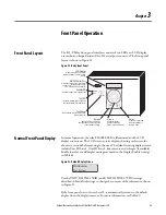
Front Panel Operation
Chapter
3
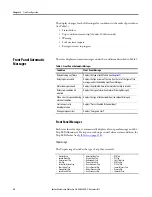
Alarm or Warning Messages
Each time the relay is in a warning condition with the Trip LED flashing, the
front-panel displays the corresponding warning message.
The Warning message describes the type of warning that is occurring:
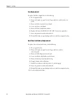
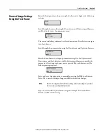
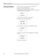
The relay automatically displays a thermal time to trip for an impending thermal
overload. See Figure 24.
Figure 24 - Trip Message Sample
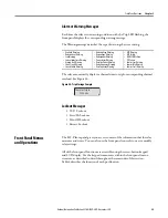
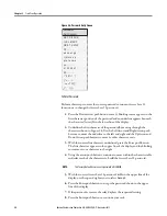
Lockout Messages
•
TCU Lockout
•
Start/Hr Lockout
•
Min Off Lockout
•
Restart Lockout
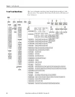
Front Panel Menus
and Operations
The 825-P front panel gives you access to most of the information that the relay
measures and stores. You can also use the front panel controls to view or modify
relay settings.
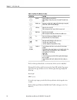
All of the front panel functions are accessible using the seven-button keypad
and LCD display. Use the keypad to maneuver within the front panel’s menu
structure, as described in detail throughout the remainder of this section.
Table 4 describes the function of each push button.
•
Overload Warning
•
Undercurrent Warning
•
Jam Warning
•
Current Imbalance Warning
•
Ground Fault Warning
•
Short Circuit Warning
•
Speed Switch Warning
•
Undervoltage Warning
•
Overvoltage Warning
•
Underpower Warning
•
Power Factor Warning
•
Reactive Power Warning
•
Underfrequency Warning
•
Overfrequency Warning
•
RTD Warning
•
RTD Failure
•
MCM/CWE Failure
•
PTC Failure
•
Comm. Loss Warning
•
Comm. Idle Warning
•
Comm. Fault Warning
Thermal Trip In
1234 sec
Summary of Contents for 825-P
Page 1: ...Modular Protection System for Motors Catalog Number 825 P User Manual...
Page 4: ...4 Rockwell Automation Publication 825 UM004D EN P November...
Page 64: ...64 Rockwell Automation Publication825 UM004D EN P November 2012 Chapter 5 Using MPS Explorer...
Page 234: ...234 Rockwell Automation Publication 825 UM004D EN P April 2012 Chapter B ParameterList...
Page 265: ......


