74
Rockwell Automation Publication 825-UM004D-EN-P - November 2012
Chapter 6
Configuring Protection & Logic Functions
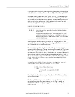
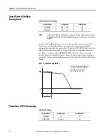
Motor running and stopped cooling times or time constants could be provided
by the motor manufacturer. If a time constant is provided, multiply that value
by 3 to calculate the STOP COOL TIME setting.
OL RESET MODE determines the reset mode for the overload element. If set
to Auto, the overload trip resets automatically when the element resets, provided
no other trip conditions are present. If set to Manual, operator intervention is
required to reset the overload trip.
OL RESET LEVEL determines the Thermal Capacity Utilized (%TCU) Level
below which the relay allows Reset (Automatic or Manual) following an overload
trip.
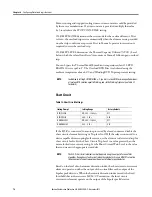
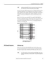
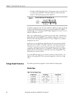
You can bypass the Thermal Model by ambient temperature when OL RTD
BIASING is set equal to Y. The Overload RTD Bias is calculated using the
ambient temperature above 40°C and Winding RTD Trip temperature setting.
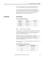
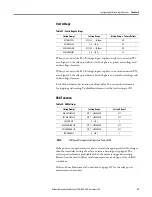
Short Circuit
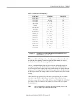
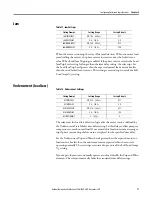
Table 13 - Short Circuit Settings
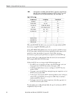
If the 825-P is connected to a motor protected by a fused contactor, disable the
short circuit element by setting its Trip level to Off. If the relay is connected to a
device capable of interrupting fault current, use the element to detect and trip for
short circuit faults. Set the Short Circuit Trip Level to a value greater than the
motor locked rotor current rating. Set the Short Circuit Warn Level to the value
that you want with appropriate time delay.
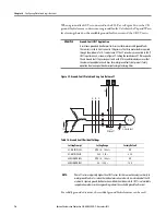
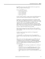
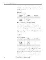
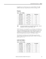
Based on the level of an harmonic distortion index, the short circuit overcurrent
elements operate on either the output of the cosine filter or the output of the
bipolar peak detector. When the harmonic distortion index exceeds the fixed
threshold that indicates severe MCM/CT saturation, the short circuit
overcurrent elements operate on the output of the bipolar peak detector.
NOTE:
In addition to setting OL RTD BIASING := Y, you must set one RTD Location equal to Ambient,
at least one RTD Location equal to Winding, and set the Winding Trip Level (see Table 27
for details).
Setting Prompt
Setting Range
Factory Default
SC TRIP LEVEL
Off, 4.00…12.00 x
I
e
Off
SC TRIP DELAY
0.00…5.00 s
0.00
SC WARN LEVEL
Off, 4.00…12.00 x
I
e
Off
SC WARN DELAY
0.00…5.00 s
0.50
NOTE:
The 825-P short circuit elements normally operate using the output of a cosine filter
algorithm. During heavy fault currents when the relay detects severe MCM/CT saturation
the overcurrent elements operate on the output of a bipolar peak detector.
Summary of Contents for 825-P
Page 1: ...Modular Protection System for Motors Catalog Number 825 P User Manual...
Page 4: ...4 Rockwell Automation Publication 825 UM004D EN P November...
Page 64: ...64 Rockwell Automation Publication825 UM004D EN P November 2012 Chapter 5 Using MPS Explorer...
Page 234: ...234 Rockwell Automation Publication 825 UM004D EN P April 2012 Chapter B ParameterList...
Page 265: ......

