background image

Installation Instructions

Publication 1792D-5.20 - October 1998

ArmorBlock MaXum 8 Input / 8 Output 
Module

(Cat. No. 1792D-8BVT8D)

This ArmorBlock MaXum

 I/O module (Cat. No. 1792D-8BVT8D) is a 

stand-alone 24V dc I/O product which communicates via a DeviceNet 
network. The sealed housing of this module requires no enclosure. 

This model has 8 inputs and 8 outputs accessed through Y splitter cables. 
Inputs are 24V dc automatically configured for PNP (sourcing) or NPN 
(sinking) devices. Eight self-protected 24V dc outputs can provide up to 
0.5 amp each. Diagnostic features included are short circuit, open wire and 
no load detection reported to the point level.

Package Contents

Your package contains:

• 1 ArmorBlock MaXum Module

• Installation Instructions

(Please note: Cable bases are ordered and shipped separately.) 

I-4

O-4

I-5

O-5

I-2

O-2

I-3

O-3

I-0

O-0

I-1

O-1

I-6

O-6

I-7

O-7

Module Status

Network Status

Auxilary Power

41516

AB Parts

Summary of Contents for ArmorBlock MaXum 1792D-8BVT8D

Page 1: ...cessed through Y splitter cables Inputs are 24V dc automatically configured for PNP sourcing or NPN sinking devices Eight self protected 24V dc outputs can provide up to 0 5 amp each Diagnostic features included are short circuit open wire and no load detection reported to the point level Package Contents Your package contains 1 ArmorBlock MaXum Module Installation Instructions Please note Cable b...

Page 2: ...081 2 EMC Generic Emission Standard Part 2 Industrial Environment EN 50082 2 EMC Generic Immunity Standard Part 2 Industrial Environment This product is intended for use in an industrial environment Low Voltage Directive This product is tested to meet Council Directive 73 23 EEC Low Voltage by applying the safety requirements of EN 61131 2 Programmable Controllers Part 2 Equipment Requirements and...

Page 3: ...odule The two switches are MSD most significant digit LSD least significant digit To reset the node address use a small blade screwdriver to rotate the switches Line up the small black dot on the switch with the number setting you wish to use The rotary switches are read at module power up only Settings between 64 and 99 cause the module to use the last valid node address stored internally Example...

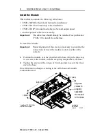
Page 4: ...ase To install the module Important Proper alignment of the screws is necessary to complete the connections between the module contacts and the cable contacts 1 Position the module over the mounted cable base Align the three cap tive screws in the module with the accepting receptacles in the base 2 Tighten the screws with a torque of 8 inch pounds to secure the mod ule to the base Note Dimensions ...

Page 5: ...for the connectors are shown next ATTENTION Make sure all connectors and caps are securely tightened to properly seal the connections against leaks and maintain IP67 requirements For maximum noise immunity input and output cable return wires must be properly terminated When inputs and outputs are connected in loopback return wires should be connected together I O cable length should be less than 3...

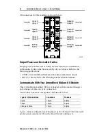
Page 6: ...nged with the master through a poll change of state or cyclic connection The module consumes and produces I O data as follows Cyclic allows configuration of the block as an I O client The block will produce and consume its I O cyclically at the rate configured Type of I O Connections Consumes Produces Cyclic 1 Byte 4 Bytes Polled 1 Byte 4 Bytes Change of State 1 Byte 4 Bytes I 4 I 5 I 6 I 7 O 4 O ...

Page 7: ...ces 3 RSVD OPWR RSVD RSVD RSVD RSVD RSVD RSVD Consumes 0 O7 O6 O5 O4 O3 O2 O1 O0 Where OW Off Wire RSVD Reserved I Input O Output OPWR Output Power Auxiliary Power OFLT Output fault ISC Input Short Circuit in Sensor Source Voltage Byte Bit Description Produces 0 00 07 Input Status bits When the bit is set 1 the input is on Bit 00 corresponds to input 0 bit 01 corresponds to input 1 bit 02 correspo...

Page 8: ...LT0 corresponds to output 0 OFLT1 corresponds to output 1 OFLT2 corresponds to output 2 OFLT3 corresponds to output 3 OFLT4 corresponds to output 4 OFLT5 corresponds to output 5 OFLT6 corresponds to output 6 OFLT7 corresponds to output 7 Produces 3 00 05 06 07 RSVD Reserved Output Power Fault OPWR When the bit is set 1 Auxiliary Power is not present RSVD Reserved Consumes 0 00 07 Output bits When ...

Page 9: ...erating Normal Red Blinking Solid Recoverable Fault Unrecoverable Fault I 4 I 5 I 6 I 7 O 4 O 5 I 2 I 3 O 2 O 3 O 6 O 7 Network Status Module Status I 0 I 1 O 0 O 1 Auxiliary Power 41517 Point indicators for inputs 0 and 1 DeviceNet Indicators Connector A Connector B Connector C Connector D Connector E Connector F Connector G Connector H Point indicators for inputs 2 and 3 Point indicators for inp...

Page 10: ...iliary Power Present I O Status Indicators Function Module Status Indicator Point Indicator1 Condition Outputs Green Green Module Status blink red Module Status blink red Module Status blink red Module Status blink red None Yellow Orange Red Orange Red Output not energized Output energized Output shorted auto restart Output shorted latching Output no load auto restart Output no load latching Input...

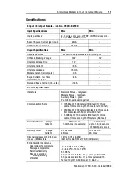
Page 11: ...red green Auxiliary Power green Point LED yellow orange red Communication Rate 125Kbps 500 meters 1600 feet for thick cable flat media length 375 meters 1230 feet 250Kbps 200 meters 600 feet for thick cable flat media length 150 meters 492 feet 500Kbps 100 meters 330 feet for thick cable flat media length 75 meters 246 feet DeviceNet Power Voltage Current 25V dc max 150mA max no sensors 11V dc min...

Page 12: ...ply with ODVA Conformance Test Software Composite Test Version 11 ArmorBlock ArmorBlock MaXum and DeviceNetManager are trademarks of Rockwell Automation General Specifications Conductors Publication DN 6 7 2 Enclosure Meets or exceeds IP67 Agency Certification when product is marked CSA certified CSA Class 1 Division 2 Groups A B C D certified UL listed CE marked for all applicable directives Prod...

Reviews: