background image

2

    ControlLogix AC (10-265V) DC (5-150V) Isolated Relay Module 

Publication

 1756-IN513D-EN-P - November 2003

Important User Information

Solid state equipment has operational characteristics differing from those of electromechanical 
equipment. 

Safety Guidelines for the Application, Installation and Maintenance of Solid State Controls


(Publication SGI-1.1 available from your local Rockwell Automation sales office or online at 
http://www.ab.com/manuals/gi) describes some important differences between solid state equipment 
and hard-wired electromechanical devices. Because of this difference, and also because of the wide 
variety of uses for solid state equipment, all persons responsible for applying this equipment must 
satisfy themselves that each intended application of this equipment is acceptable.
In no event will Rockwell Automation, Inc. be responsible or liable for indirect or consequential damages 
resulting from the use or application of this equipment.
The examples and diagrams in this manual are included solely for illustrative purposes. Because of the 
many variables and requirements associated with any particular installation, Rockwell Automation, Inc. 
cannot assume responsibility or liability for actual use based on the examples and diagrams.
No patent liability is assumed by Rockwell Automation, Inc. with respect to use of information, circuits, 
equipment, or software described in this manual.
Reproduction of the contents of this manual, in whole or in part, without written permission of Rockwell 
Automation, Inc. is prohibited.
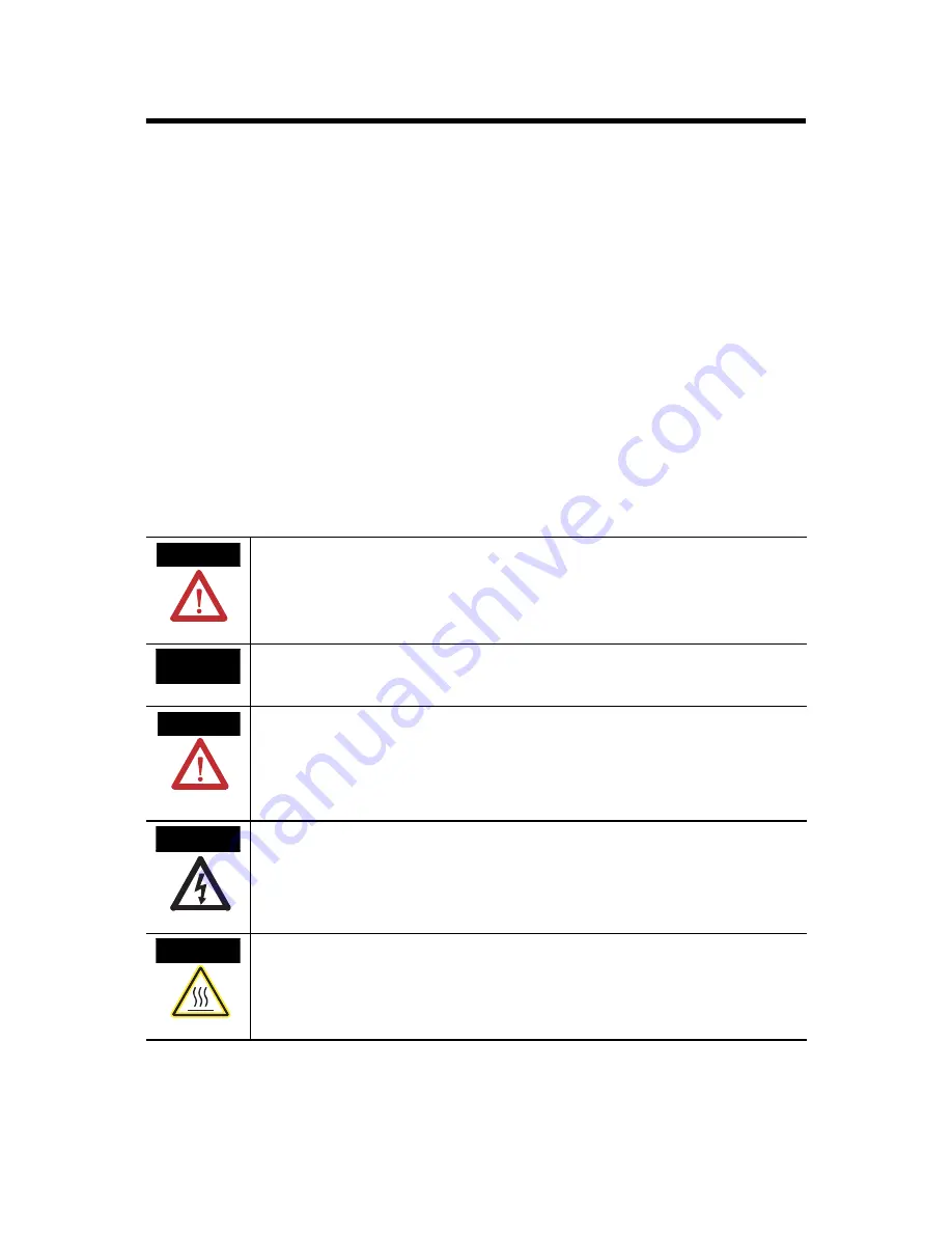
Throughout this manual we use notes to make you aware of safety considerations.

WARNING

Identifies information about practices or circumstances that can cause an explosion in a 
hazardous environment, which may lead to personal injury or death, property damage, 
or economic loss.

IMPORTANT

Identifies information that is critical for successful application and understanding of the 
product.

ATTENTION

Identifies information about practices or circumstances that can lead to personal injury 
or death, property damage, or economic loss. Attentions help you:

identify a hazard

avoid a hazard

recognize the consequence

SHOCK HAZARD

Labels may be located on or inside the drive to alert people that dangerous voltage may 
be present.

BURN HAZARD

Labels may be located on or inside the drive to alert people that surfaces may be 
dangerous temperatures.

Summary of Contents for ControlLogix 1756-OX8I

Page 1: ... visit www theautomationbookstore com and place an order call 800 963 9548 USA Canada or 001 320 725 1574 outside USA Canada To See page Identify the Module Components 7 Note the Power Requirements 7 Install the Module 8 Key the Module and Removable Terminal Block Interface Module 9 Wire the Removable Terminal Block 10 Wire the Module 11 Assemble the Removable Terminal Block and the Housing 12 Ins...

Page 2: ...ments associated with any particular installation Rockwell Automation Inc cannot assume responsibility or liability for actual use based on the examples and diagrams No patent liability is assumed by Rockwell Automation Inc with respect to use of information circuits equipment or software described in this manual Reproduction of the contents of this manual in whole or in part without written permi...

Page 3: ...of the enclosure must be accessible only by the use of a tool Subsequent sections of this publication may contain additional information regarding specific enclosure type ratings that are required to comply with certain product safety certifications NOTE See NEMA Standards publication 250 and IEC publication 60529 as applicable for explanations of the degrees of protection provided by different ty...

Page 4: ...stries Electriques certifies that this equipment has been found to comply with the Essential Health and Safety Requirements relating to the design and construction of Category 3 equipment intended for use in potentially explosive atmospheres given in Annex II to this Directive The examination and test results are recorded in confidential report No 28 682 010 Compliance with the Essential Health an...

Page 5: ...to help determine the overall temperature code of the system Combinations of equipment in your system are subject to investigation by the local Authority Having Jurisdiction at the time of installation Les produits marqués CL I DIV 2 GP A B C D ne conviennent qu à une utilisation en environnements de Classe I Division 2 Groupes A B C D dangereux et non dangereux Chaque produit est livré avec des m...

Page 6: ...changed in an area known to be nonhazardous AVERTISSEMENT RISQUE D EXPLOSION Couper le courant ou s assurer que l environnement est classé non dangereux avant de débrancher l équipement Couper le courant ou s assurer que l environnement est classé non dangereux avant de débrancher les connecteurs Fixer tous les connecteurs externes reliés à cet équipement à l aide de vis loquets coulissants connec...

Page 7: ...documentation that came with it to connect wiring Note the Power Requirements This module receives power from the 1756 chassis power supply and requires 2 sources of power from the ControlLogix backplane 100mA at 5 1V dc 100mA at 24V dc Add this current power value 2 9W to the requirements of all other modules in the chassis to prevent overloading the power supply Field output supply power should ...

Page 8: ...auses excessive wear to contacts on both the module and its mating connector Worn contacts may create electrical resistance that can affect module operation 1 Align the circuit board with the top and bottom chassis guides 2 Slide the module into chassis until module locking tabs click WARNING When you insert or remove the module while backplane power is on an electrical arc can occur This could ca...

Page 9: ... on the module that correspond to unkeyed positions on the RTB For example if you key the first position on the module leave the first position on the RTB unkeyed 1 To key the module insert the U shaped band as shown 2 Push the band until it snaps in place 3 To key the RTB or IFM insert the wedge shaped tab with rounded edge first as shown 4 Push the tab until it stops Reposition the tabs to rekey...

Page 10: ...ect or disconnect the Removable Terminal Block RTB while field side power is on an electrical arc can occur This could cause an explosion in hazardous location installations Spring Clamp RTB Cage Clamp RTB 20860 M 20859 M 1 Strip 7 16 inch 11mm maximum length of wire 2 Insert the screwdriver into the inner hole of the RTB 3 Insert the wire into the open terminal and remove the screwdriver 1 Strip ...

Page 11: ... N C OUT 3 N O Not used OUT 4 N O OUT 5 N C OUT 5 N O OUT 6 N C OUT 6 N O OUT 7 N C OUT 7 N O Not used L1 Jumper bar Cut to length Part number 97739201 DC 2 L2 L1 7 L2 0 DC 2 L1 0 NOTES 1 All terminals with the same name are connected together on the module For example L1 0 can be connected to either terminal marked L1 0 2 Do not physically connect more than two wires to a single RTB terminal When...

Page 12: ... the top of the module is unlocked WARNING If you connect or disconnect the Removable Terminal Block RTB with field side power applied an electrical arc can occur This could cause an explosion in hazardous location installations 20858 M Groove Groove Side edge of the RTB Side edge of the RTB Strain relief area 1 Align the grooves at the bottom of the housing with the side edges of the RTB 2 Slide ...

Page 13: ... OFF This completes installation of the module Use the following information to remove the module if necessary Indicator Displaying Means Take this action OK Steady green light The outputs are actively being controlled by a system processor None OK Flashing green light The module has passed internal diagnostics but is not actively controlled Configure the module OK Flashing red light Previously es...

Page 14: ...TB Remove the Module WARNING When you insert or remove the module while backplane power is on an electrical arc can occur This could cause an explosion in hazardous location installations Be sure that power is removed or the area is nonhazardous before proceeding 20855 M 2 Open the RTB door and pull the RTB off the module 1 Unlock the locking tab at the top of the module 42517 1 Push in top and bo...

Page 15: ... ac 2 0A resistive Output Current Rating at rated power Resistive Inductive 2A 5 30V dc 2 0A steady state 5 30V dc 0 5A 48V dc 0 5A steady state 48V dc 0 25A 125V dc 0 25A steady state 125V dc 2A 125V ac 2 0A steady state 15A make 125V ac 2A 240V ac 2 0A steady state 15A make 240V ac Power Rating steady state 250W maximum for 125V ac resistive output 480W maximum for 240V ac resistive output 60W m...

Page 16: ...Scheduled Outputs Synchronization within 16 7 seconds maximum reference to the Coordinated System Time Configurable Fault States Point Hold Last State ON or OFF OFF is the default Config States in Program Mode Point Hold Last State ON or OFF OFF is the default Fusing Not protected Fused IFM is recommended to protect outputs See publication 1492 2 12 Isolation Voltage Channel to channel User to sys...

Page 17: ...tive Humidity IEC 60068 2 30 Test Db Un packaged Non operating Damp Heat 5 to 95 non condensing Vibration IEC 60068 2 6 Test Fc Operating 5g 10 500Hz Operating Shock IEC 60068 2 27 Test Ea Unpackaged Shock 30g Non Operating Shock IEC 60068 2 27 Test Ea Unpackaged Shock 50g Emissions CISPR 11 Group 1 Class A ESD Immunity IEC 61000 4 2 6kV contact discharges 8kV air discharges Radiated RF Immunity I...

Page 18: ...2 Industrial Immunity EN 61326 Meas Control Lab Industrial Requirements EN 61000 6 2 Industrial Immunity EN 61000 6 4 Industrial Emissions European Union 73 23 EEC LVD Directive compliant with EN 61131 2 Programmable Controllers C Tick 3 Australian Radiocommunications Act compliant with AS NZS CISPR 11 Industrial Emissions EEx 3 European Union 94 9 EC ATEX Directive compliant with EN 50021 Potenti...

Page 19: ...ControlLogix AC 10 265V DC 5 150V Isolated Relay Module 19 Publication 1756 IN513D EN P November 2003 Notes Allen Bradley ...

Page 20: ...sit http support rockwellautomation com Installation Assistance If you experience a problem with a hardware module within the first 24 hours of installation please review the information that s contained in this manual You can also contact a special Customer Support number for initial help in getting your module up and running New Product Satisfaction Return Rockwell tests all of our products to e...

Reviews: