Rockwell Automation Publication SAFETY-AT140A-EN-P - May 2015
3
Safety Function: Actuator Subsystems – Stop Category 1 via the PowerFlex 525 and PowerFlex 527 Drives with Safe Torque-off
General Safety Information
Contact Rockwell Automation to find out more about our safety risk assessment services.
Introduction
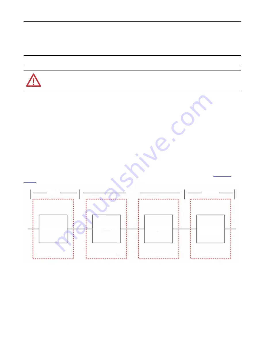
This safety function application technique is concerned primarily with the Logic and Output subsystems of a safety system.
The document illustrates how to combine a Guardmaster® dual-input safety relay (GSR DI) and Guardmaster
multifunction-delay expansion module (GSR EMD) with a PowerFlex® 525 drive or a PowerFlex 527 drive to provide a
category 1 stop. The category 1 stop provides a brief delay between the stop request to the programmable automation
controller (PAC) and the de-energizing of the STO inputs to allow the system time to execute an orderly stop before the
STO inputs are de-energized. The intent is to provide a less disruptive, but safe, response to a sudden emergency stop
demand.
In an actual application, any typical safety input device could be used as the Input subsystem if properly applied. A
SensaGuard™ switch, as in Safety Function: Door Monitoring Products: SensaGuard/GSR DI, publication
, is used as a convenient example of an Input subsystem in this application technique.
Safety Function Realization: Risk Assessment
The required performance level is the result of a risk assessment and refers to the amount of the risk reduction to be carried
out by the safety-related parts of the control system. Part of the risk reduction process is to determine the safety functions of
the machine. In this application, the performance level required (PLr) by the risk assessment is Category 3, Performance
Level d (CAT. 3, PLd), for each safety function. A safety system that achieves CAT. 3, PLd, or higher, can be considered
IMPORTANT
This application example is for advanced users and assumes that you are trained and experienced in safety system requirements.
ATTENTION:
Perform a risk assessment to make sure all task and hazard combinations have been identified and addressed. The risk
assessment can require additional circuitry to reduce the risk to a tolerable level. Safety circuits must take into consideration safety
distance calculations, which are not part of the scope of this document.
Input
Logic
Output
Subsystem 1
Subsystem 2
Subsystem 3
Subsystem 4
SensaGuard
Switch
Guardmaster
Dual-input
Safety Relay
Guardmaster
Expansion
Module
PowerFlex
527 Drive


