2
Rockwell Automation Publication 20Y-IN004A-EN-P - October 2014
PowerFlex Active Front End in IP20 2500 MCC Style Enclosure Frame 13 Right-Side Bus Splice Kit
Where the Kit Is Used
This kit can be used with only an Active Front End Frame 13 in an IP20 2500
MCC Style enclosure to connect bus bars to only an adjacent right side IP20
2500 MCC Style enclosure that has the same bus bar alignment. This provides an
in-line common bus system configuration.
What the Kit Contains
ATTENTION:
To avoid an electric shock hazard, verify that the voltage on the
bus capacitors has discharged completely before performing any work on the
Active Front End. After power is removed from the Active Front End, wait 5
minutes for the bus capacitors to discharge. Check the DC bus voltage between
the DC+ and DC- terminals, between the DC+ terminal and the chassis, and
between the DC- terminal and the chassis. The measured voltage must be zero
for all three measurements.
ATTENTION:
To guard against personal injury and or equipment damage
caused by an ARC Flash, the user must identify the ARC Flash requirements per
NFPA 70E.
ATTENTION:
If you do not follow ESD control procedures, the PowerFlex Active
Front End, which contains electrostatic discharge (ESD) sensitive parts and
assemblies, can be damaged. Static control precautions are required when
installing, testing, servicing, or repairing the Active Front End. If you are
unfamiliar with static control procedures, see Guarding Against Electrostatic
Damage, publication 8000-4.5.2, or any other applicable ESD protection
handbook.
ATTENTION:
An incorrectly applied or installed Active Front End can result in
component damage or a reduction in product life. Wiring or application errors
such as undersizing the motor, incorrect or inadequate AC supply, or excessive
ambient temperatures can result in malfunction of the system.
ATTENTION:
The user is responsible for conforming with all applicable local,
national, and international codes. Failure to observe this precaution can result
in damage to, or destruction of, the equipment.
ATTENTION:
Only qualified personnel familiar with the construction and
operation of this equipment and the hazards that are involved must plan or
implement system installation, startup, and subsequent maintenance. Failure
to comply can result in personal injury and/or equipment damage.
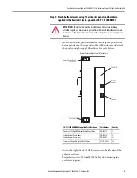
SK-Y1-BUSSPLICE-F13R Kit Supplied Parts/Hardware
Part Number
Quantity
PowerFlex 750 High HP Ground Splice
PN-226139
2
MCC Centerline Right-side Bus Splice
PN-243215
6
Washer, Flat, 3/8 in.
M-353
16
MCC Bus Clamp Assembly
40319-400-05
8
Hex Nut, Conical Spring Washer, M10 x 10.1 mm
29360-527-01
16
Screw, Hex Flange HD, Taptite, M6 x 20 mm (for PE connection only)
29171-640-02
8

