background image

RDD-Series Rotary Direct Drive Bearingless Motor Installation Instructions     

11

Publication RDB-IN002A-EN-P — October 2009

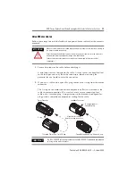
Verify Machine Mounting Dimensions 

Verify proper fit of the motor to the machine mount by measuring the following 
machine mounting dimensions: 

1.

Verify these dimensions are within the measurement range in the tables: 

• Pilot diameter 

• Shaft diameter, large and small 

• Shaft length, small and overall 

2.

Verify the Total Indicator Readout (TIR) of these dimensions is less than the 
value in the tables when measured with a dial indicator: 

• Shaft runout 

• Pilot concentricity 

• Mounting surface perpendicularity 

Machine Mounting Dimensions

Machine 

Mounting 

Surface 

Small Shaft 
Diameter 

Large Shaft 

Diameter 

Pilot 

Diameter 

Small Shaft Length

Overall Shaft Length

Pilot 
Extension 

Summary of Contents for RDB-B2901

Page 1: ...tors RDD Series direct drive motors feature single turn or multi turn high resolution encoders These bearingless housed motors provide a compact design for direct drive applications Topic Page Important User Information 2 Catalog Number Explanation 3 Before You Begin 4 Install the Motor 9 Remove the Motor 19 Connector Data 26 Product Dimensions 27 Specifications 30 Additional Resources 31 ...

Page 2: ... any particular installation Rockwell Automation Inc cannot assume responsibility or liability for actual use based on the examples and diagrams No patent liability is assumed by Rockwell Automation Inc with respect to use of information circuits equipment or software described in this manual Reproduction of the contents of this manual in whole or in part without written permission of Rockwell Aut...

Page 3: ... Bore T IP64 Housing Thru Bore FEEDBACK 3 Single turn High Resolution Heidenhain 7 Multi turn High Resolution Heidenhain NOMINAL SPEED 4 200 rpm 440V 5 250 rpm 440V 6 375 rpm 440V 8 625 rpm 440V 9 750 rpm 440V MAGNET STACKS 1 One Stack 2 Two Stacks 3 Three Stacks FRAME SIZE Bolt Circle Diameter 290 290 mm 410 410 mm VOLTAGE RATING A 200V Class B 400V Class HOUSING TYPE DB Direct Drive Bearingless ...

Page 4: ...ainer 2 Visually inspect the motor mounting pilot and encoder for damage 3 Notify the carrier of any shipping damage immediately 4 Retain the cardboard cover and protective paper sleeving from the mounting end of the motor ATTENTION The mounting end of the motor exposes magnetized material within the motor Accidental entry of foreign material will harm motor performance Always cover the mounting e...

Page 5: ...oving this product Tools Required for Installation Value Hex bit 150 mm 6 in minimum length 6 mm Torque wrench Capable of applying at least 65 N m 50 lb ft Screwdriver Phillips 2 Micrometer N A Straight edge Caliper Runout indicator Cleaning cloth Shaft key provided Additional Tools Required for Removal Value M6 x 1 x 120 hex bolt or rod For RDB B4103 motor only Qty 1 M10 and M12 hex bolts Qty 2 m...

Page 6: ...mmonly called electrical noise can reduce motor performance Effective techniques to counter EMI include filtering the AC power using shielded cables separating signal cables from power wiring and practicing good grounding techniques Follow these guidelines to avoid the effects of EMI Isolate the power transformers or install line filters on all AC input power lines Physically separate signal cable...

Page 7: ... both ends of the encoder cable shield and twist the signal wire pairs to prevent electromagnetic interference EMI from other equipment WARNING Do not tightly gather or coil the excess length of a power cable Heat is generated within a cable whenever power is applied Always position a power cable so it may freely dissipate any heat A power cable should not be coiled except for temporary use when b...

Page 8: ...0 XXNPMF xxSxx contains two signal wire pairs 2 Clamp all signal wire shields and the overall power cable shield in the power cable chassis ground clamp on the drive Grounding of Signal Wire Shields in a Power Cable SHOCK HAZARD If any shield on a power cable is not grounded high voltage can be present on that shield Make sure there is a connection to ground for all shield wires inside a power cab...

Page 9: ...tor remove the shaft key and other mechanical couplings that could be thrown from the shaft Failure to observe these safety precautions could result in personal injury ATTENTION Servo drive power must be turned off before connecting or disconnecting the cables to the motor and if a cable is left disconnected at the motor end Arcing or unexpected motion could occur if the feedback power or brake ca...

Page 10: ...ross the motor and keep other heat producing devices away from the motor Heatsink requirements are listed in a footnote to the Specifications table 2 Wipe the shaft and the rotor hub to remove excess grease or other contaminants A light oil coating is acceptable Outer surfaces of a motor can reach high temperatures 125 C 275 F during operation Take precautions to prevent accidental contact with ho...

Page 11: ...re within the measurement range in the tables Pilot diameter Shaft diameter large and small Shaft length small and overall 2 Verify the Total Indicator Readout TIR of these dimensions is less than the value in the tables when measured with a dial indicator Shaft runout Pilot concentricity Mounting surface perpendicularity Machine Mounting Dimensions Machine Mounting Surface Small Shaft Diameter La...

Page 12: ...2 mm 3 480 3 600 in 132 61 135 61 mm 5 220 5 340 in 169 19 172 19 mm 6 660 6 780 in Shaft Runout 0 038 mm 0 0015 in max Pilot Concentricity 0 05 mm 0 002 in max Mounting Surface Perpendicularity 0 05 mm 0 002 in max Attribute Value Pilot Diameter 333 94 333 98 mm 13 147 13 149 in Shaft Diameter Small 69 988 69 999 mm 2 7554 2 7559 in Shaft Diameter Large 79 988 79 999 mm 3 1491 3 1496 in Shaft Len...

Page 13: ...ition the motor on the pilot extension of the machine 4 Rotate the motor on the machine shaft to align the mounting holes with those on the machine 5 Insert a fastener in each of the four 4 mounting holes in the motor faceplate and hand tighten each fastener to secure the motor to the machine frame 6 Using an alternating pattern tighten each fastener within the recommended torque range IMPORTANT W...

Page 14: ...r Loosen each pan head screw with a Phillips screwdriver The RDB x290x motor has eight 8 screws to loosen The RDB x410x motor has eleven 11 screws to loosen IMPORTANT Do not attempt to remove the pan head screws from the cover The screws are attached to the end cover with a mechanical lock ring Foam Holder for Shipping Hardware End Cover ...

Page 15: ...lb in 1x 13 N m 10 lb ft 2x 20 N m 15 lb ft 2x 30 N m 22 lb ft 2x 30 N m 22 lb ft Until no bolt moves IMPORTANT The torque sequence requires at least eight steps to secure the compression coupling on the machine shaft Each step gradually increases the torque value until the final value is attained Several steps are performed a more than once to verify the torque force is applied evenly to all bolt...

Page 16: ... each screw in the foam holder There are four 4 set screws total Refer to the diagram on page 15 for the location of each hole C 3 Rotate the shaft or load by hand to verify free rotation of the motor Replace the End Cover Follow these steps to align and secure the end cover in its original position 1 Verify the O ring is undamaged and in position around the inside edge of the cover 2 Carefully po...

Page 17: ... creates a more secure connection for a cable with a threaded plug O rings interior to the threaded and SpeedTec plug provide complete environmental sealing for the cable ATTENTION Make sure that cables are installed and restrained to prevent uneven tension or flexing at the motor to cable connections Excessive and uneven lateral force at the motor connectors can result in the connector s environm...

Page 18: ... do not go together with light hand force realign the flat surfaces and try again IMPORTANT The connector orientation shown is used to clearly show the alignment marker on each cable socket The recommended orientation when installed positions the connectors at the bottom of the motor TIP A fully seated threaded plug leaves a small opening approximately 1 4 mm 0 04 0 16 in between the connector and...

Page 19: ...temperature when selecting connections and cables to install on a motor Failure to observe safety precautions could result in personal injury or damage to equipment ATTENTION Servo drive power must be turned off before connecting or disconnecting the cables to the motor and if a cable is left disconnected at the motor end Arcing or unexpected motion could occur if the feedback power or brake cable...

Page 20: ... diagrams on page 15 2 Turn the shaft by hand until a threaded hole directly aligns with each hole B and the hex bolts on the compression coupling are visible through each hole A 3 Verify each hole C shows the flat surface of the rotor The holes are not evenly spaced If necessary continue to slowly rotate the shaft until the above conditions are met IMPORTANT Correct alignment of holes A and B is ...

Page 21: ...ert it in a hole C There are four 4 set screws total Refer to the diagram on page 15 for the locations 2 Tighten each set screw to 0 1 N m 1 lb in by hand with a 6 mm hex bit 3 Remove each shipping bolt from the foam holder and insert it in a hole B There are four 4 shipping bolts total Refer to the diagram on page 15 for the locations 4 Tighten each shipping bolt to 16 0 N m 142 lb ft with a 6 mm...

Page 22: ...ling bolts through the holes labelled A The RDB x290x motor has six 6 compression bolts to loosen The RDB x410x motor has ten 10 compression bolts to loosen Refer to the diagram on page 15 for the locations 2 Moving in a circular pattern use a 6 mm hex bit to loosen each compression coupling bolt 3 Loosen each bolt two 2 revolutions beyond finger tight WARNING Loosening the compression coupling bo...

Page 23: ...ps 1 and 2 to the compression coupling bolt directly opposite the bolt accessed most recently Use this alternating pattern until all compression couplings are released RDB x4103 Motors Only 1 Seat a M6 x 1 x 120 screw or threaded rod into either hole D Access the second stage compression coupling bolts on a RDB x4103 motor through the holes labelled D The RDB x410x motor has two 2 second stage com...

Page 24: ...cure the end cover on the motor The RDB x290x motor has eight 8 screws to tighten The RDB x410x motor has eleven 11 screws to tighten Remove the Motor From the Machine Follow these steps to remove the motor from the machine shaft 1 Remove the four 4 mounting bolts securing the motor frame to the machine 2 Slide the motor off the machine shaft TIP If the motor is locked to the machine use the threa...

Page 25: ...paper sleeving around the rotor 2 Cover the opening at the mounting end of the motor with the cardboard cover that came with the motor ATTENTION The mounting end of the motor contains magnetized materials that can attract metallic materials Accidental entry of foreign material can harm motor performance Always cover the mounting end of motor immediately after removing the motor This prevents forei...

Page 26: ...gnal Name Pin Signal Name Pin Signal Name 1 Sin A Phase U U Phase U 2 Sin B Phase V V Phase V 3 Cos C Phase W W Phase W 4 Cos Ground Ground 5 Data E Reserved Reserved 6 Data F 7 CLK G 1 8 CLK H 2 9 EPWR 5V L 10 ECOM 11 Reserved 12 Reserved 13 TS 14 TS 15 Reserved 16 17 W V U 1 2 Intercontec P N CEDE271NN00000051000 Intercontec P N AEDC113NN00000202000 1 2 3 4 5 6 7 8 9 10 11 12 13 14 17 15 16 Inte...

Page 27: ...P October 2009 Product Dimensions The dimensions in the table are for motors with a single turn or a multi turn encoder Footnotes identify tolerances and dimensional differences T F GD G LB LE LD LA HD AD EB M Dia of Bolt Circle S Dia of Bolt Holes P DB D N E Key Key supplied with motor Orient as shown R ...

Page 28: ...r this dimension is 1 50 mm 0 06 in static 0 05 mm 0 002 in dynamic 89 92 3 540 134 11 5 280 170 69 6 720 114 05 4 490 167 89 6 610 253 49 9 980 F 11 957 12 000 0 4707 0 4724 G 24 80 24 99 0 976 0 984 29 80 29 99 1 173 1 181 GD 7 90 8 00 0 311 0 315 HD max 305 9 12 05 432 1 17 01 LA 3 3 Tolerance for this dimension is 2 15 mm 0 085 in 22 2 0 88 25 4 1 00 LB 4 4 Tolerance for this dimension is 2 3 ...

Page 29: ... RDB IN002A EN P October 2009 Motor Dimensions cont Dimension mm in Motor Catalog No RDB B2901 RDB B2902 RDB B2903 RDB B4101 RDB B4102 RDB B4103 P 1 1 Tolerance for this dimension is 1 52 mm 0 060 in 245 9 9 68 350 0 13 78 R 16 8 0 66 38 6 1 52 S 14 0 0 551 17 5 0 689 T 13 5 0 53 17 8 0 70 ...

Page 30: ... RDB x410 motors on a surface with heat dissipation equivalent to a 508 x 508 x 19 05 mm 20 x 20 x 0 75 in aluminum heatsink Temperature storage 30 70 C 22 158 F Relative humidity storage 5 95 noncondensing Atmosphere storage Non corrosive IP rating 1 1 The motor rating excludes any reduction in the rating resulting from cables plugs or connections with a lower rating and an unsealed customer mach...

Page 31: ...ng starting up and troubleshooting for your Kinetix 6200 servo drive system Kinetix 7000 Multi axis Servo Drives User Manual publication 2099 UM001 Information on installing configuring starting up and troubleshooting for your Kinetix 7000 servo drive system Low profile EnDat Feedback Module Installation Instructions publication 2090 IN020 Information on connecting an EnDat Feedback Module to inte...

Page 32: ...information that s contained in this manual You can also contact a special Customer Support number for initial help in getting your product up and running New Product Satisfaction Return Rockwell Automation tests all of its products to ensure that they are fully operational when shipped from the manufacturing facility However if your product is not functioning and needs to be returned follow these...

Reviews: