16
RDD-Series Rotary Direct Drive Bearingless Motor Installation Instructions
Publication RDB-IN002A-EN-P — October 2009
Remove and Secure the Shipping Hardware
Follow these steps to remove the shipping bolts and set screws that prevent rotor
movement during shipping.
1.
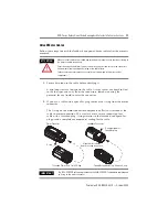
Remove the shipping bolt from each hole B using a 6 mm hex bit, and store
each bolt in the foam holder.
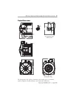
There are four (4) shipping bolts total. Refer to the diagram on
for
the location of each hole B.
2.
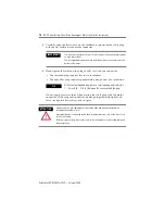
Remove the set screw from each hole C using a 6 mm hex bit, and store
each screw in the foam holder.
There are four (4) set screws total. Refer to the diagram on
location of each hole C.
3.
Rotate the shaft or load by hand to verify free rotation of the motor.
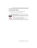
Replace the End Cover
Follow these steps to align and secure the end cover in its original position.
1.
Verify the O-ring is undamaged, and in position around the inside edge of
the cover.
2.
Carefully position the end cover over the motor opening.
3.
Rotate the end cover so the alignment mark on the cover aligns with the
corresponding mark on the motor housing.
4.
Secure the end cover by tightening the pan head screws with a Phillips
screwdriver.
• The RDB-
x
290
x
motor has eight (8) screws to tighten.
• The RDB-
x
410
x
motor has eleven (11) screws to tighten.


