4–5
Installing Your Hardware
Publication 2755-6.13
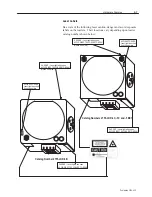
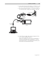
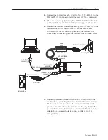
6. Connect the null modem cable (Catalog No. 2755-LHC-11) to the
PLC or PC (9–pin connector) and the reader (25–pin connector).
7. Place the power supply (Catalog No. 77126-896-01) within 12 ft.
(3.66 m) of the reader. Connect the power supply to the reader.
8. Connect the interface box cable (Catalog No. 2755-LHC-2) to the
interface box and the reader. The 15–pin end of the cable
connects to the reader and the 8–pin end to the interface box.
Make sure you lock into place the interface box end of the cable.
To PC (9-pin
connector)
To Reader (25-pin
connector)
Power
Supply
To Reader (9-pin
connector)
Grounding Pin
To Power Receptacle
Reader
To Reader (15-pin
connector)
8–pin connector
Interface Box
77126–896–01
2755–LHC–11
2755–LHC–2
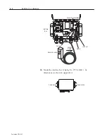
9. Connect your sensor (PhotoSwitch 6000 or 9000 Series) to the
interface box by attaching the sensor leads to the sensor terminal
block inside the interface box. The sensor itself will have the
proper connection scheme imprinted on its housing. Follow the
method shown there. For instance, brown to +12V out, white to
sink-in, blue to common, black to source. (Black is often
disregarded.)
Summary of Contents for StrataScan 2755-LHR-3C
Page 67: ...I 3 Publication 2755 6 13...


