


4–13
Installing Your Hardware
Publication 2755-6.13
!
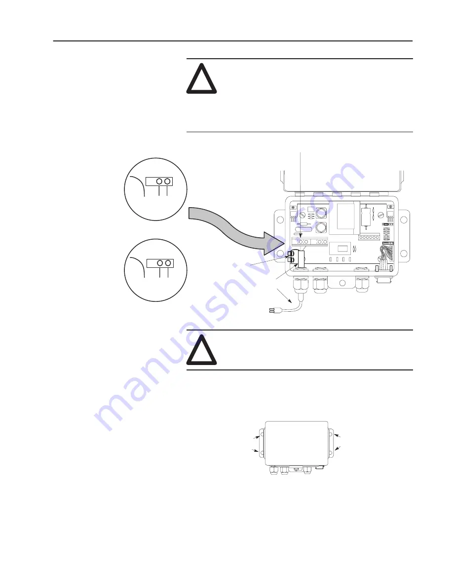
ATTENTION: Before connecting power, make sure
that the 3 power leads from the interface box power
cord are connected to their proper locations on the
power terminal block and grounding posts inside the
interface box case. A domestic and a European
example are shown in the following illustration. Make
sure that the interface box is connected to an ac source
per local/regional electrical codes.
To Power Receptacle
Power Terminal Block
Power Cable
Interface Box Cover
European 3–Wire
US 3–Wire
Color Code
Color Code
Grn Blk Wht
Grn/Yel Blue Brn
N Ln In
N Ln In
Grounding posts
To Grounding
post
To Grounding
post
!
ATTENTION: Before applying power to the interface
box, make sure the voltage selector switch is in the
correct position.
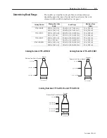
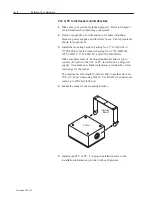
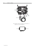
10. Mount the interface box. The dimensions of the interface box are
shown in Appendix A.
Screw Holes
Screw Holes
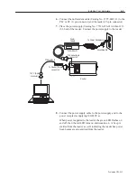
11. Connect the interface box to the power receptacle supplying
100/240V ac.
12. Connect each power supply cable to each power supply and to the
power receptacle supplying 100/240V ac.
Summary of Contents for StrataScan 2755-LHR-3C
Page 67: ...I 3 Publication 2755 6 13...


