background image

2A

PARTS

(SD) GEARBOX RIGHT HAND (SOM)

PART#: 029141 (cont’d)

2A-9

ILL.

PART #

DESCRIPTION

QTY

1.  . . . . . . . . . . . . . . . . .010513  . . . . . .GREASE SERT 1/4-28 . . . . . . . . . . . . . . . . . . . . . . . . . . . . . . . . . . .1
2.  . . . . . . . . . . . . . . . . .010038  . . . . . .BOLT, 3/8-16 X 1 1/2  . . . . . . . . . . . . . . . . . . . . . . . . . . . . . . . . . . . .12
3.  . . . . . . . . . . . . . . . . .010091  . . . . . .WASHER, LOCK 3/8  . . . . . . . . . . . . . . . . . . . . . . . . . . . . . . . . . . . .24
4.  . . . . . . . . . . . . . . . . .032745  . . . . . .PLUG, PLASTIC P-18 1/8-27 . . . . . . . . . . . . . . . . . . . . . . . . . . . . . .1
5.  . . . . . . . . . . . . . . . . .029150  . . . . . .PLATE, TOP . . . . . . . . . . . . . . . . . . . . . . . . . . . . . . . . . . . . . . . . . . .1
6.  . . . . . . . . . . . . . . . . .029184  . . . . . .TIMKEN RACE 3720  . . . . . . . . . . . . . . . . . . . . . . . . . . . . . . . . . . . .2
7.  . . . . . . . . . . . . . . . . .029183  . . . . . .TIMKEN CONE 3780  . . . . . . . . . . . . . . . . . . . . . . . . . . . . . . . . . . . .2
8.  . . . . . . . . . . . . . . . . .028914  . . . . . .SHIMS  . . . . . . . . . . . . . . . . . . . . . . . . . . . . . . . . . . . . . . . . . . . . . . .AS REQ
9.  . . . . . . . . . . . . . . . . .029148  . . . . . .GEAR, BRONZE IRON LEFT  . . . . . . . . . . . . . . . . . . . . . . . . . . . . .1
10.  . . . . . . . . . . . . . . . .029146  . . . . . .KEY, GEAR  . . . . . . . . . . . . . . . . . . . . . . . . . . . . . . . . . . . . . . . . . . .1
11. . . . . . . . . . . . . . . . . .029151  . . . . . .MAINSHAFT, LH SD  . . . . . . . . . . . . . . . . . . . . . . . . . . . . . . . . . . . .1
12.  . . . . . . . . . . . . . . . .010498  . . . . . .PLUG  . . . . . . . . . . . . . . . . . . . . . . . . . . . . . . . . . . . . . . . . . . . . . . . .4
13.  . . . . . . . . . . . . . . . .029147  . . . . . .FLANGE, GEARBOX  . . . . . . . . . . . . . . . . . . . . . . . . . . . . . . . . . . . .1
14.  . . . . . . . . . . . . . . . .010037  . . . . . .BOLT, 3/8-16 X 1 1/4  . . . . . . . . . . . . . . . . . . . . . . . . . . . . . . . . . . . .8
15.  . . . . . . . . . . . . . . . .029181  . . . . . .NATIONAL SEAL 471705 . . . . . . . . . . . . . . . . . . . . . . . . . . . . . . . . .1
16.  . . . . . . . . . . . . . . . .032713  . . . . . .RING, RETAINING UR175  . . . . . . . . . . . . . . . . . . . . . . . . . . . . . . . .1
17.  . . . . . . . . . . . . . . . .012869  . . . . . .SCREW, SET 1/4-20 X 3/8  . . . . . . . . . . . . . . . . . . . . . . . . . . . . . . .1
18.  . . . . . . . . . . . . . . . .018072  . . . . . .WASHER, FLAT 3/16 SAE . . . . . . . . . . . . . . . . . . . . . . . . . . . . . . . .3
19.  . . . . . . . . . . . . . . . .028703  . . . . . .SHROUD, FAN . . . . . . . . . . . . . . . . . . . . . . . . . . . . . . . . . . . . . . . . .1
20.  . . . . . . . . . . . . . . . .013484  . . . . . .SCREW, 10-24 X 1/2  . . . . . . . . . . . . . . . . . . . . . . . . . . . . . . . . . . . .3
21.  . . . . . . . . . . . . . . . .013740  . . . . . .WASHER, LOCK #10 . . . . . . . . . . . . . . . . . . . . . . . . . . . . . . . . . . . .3
22.  . . . . . . . . . . . . . . . .034541  . . . . . .FAN  . . . . . . . . . . . . . . . . . . . . . . . . . . . . . . . . . . . . . . . . . . . . . . . . .1
23.  . . . . . . . . . . . . . . . .028915  . . . . . .SHIMS  . . . . . . . . . . . . . . . . . . . . . . . . . . . . . . . . . . . . . . . . . . . . . . .AS REQ
24.  . . . . . . . . . . . . . . . .029272  . . . . . .TIMKEN RACE HM89410  . . . . . . . . . . . . . . . . . . . . . . . . . . . . . . . .2
25.  . . . . . . . . . . . . . . . .029182  . . . . . .TIMKEN CONE HM89443  . . . . . . . . . . . . . . . . . . . . . . . . . . . . . . . .1
26.  . . . . . . . . . . . . . . . .029529  . . . . . .VALVE, RELIEF 1/8-27 NPT  . . . . . . . . . . . . . . . . . . . . . . . . . . . . . .1
27.  . . . . . . . . . . . . . . . .029155  . . . . . .PLATE, BOTTOM . . . . . . . . . . . . . . . . . . . . . . . . . . . . . . . . . . . . . . .1
28.  . . . . . . . . . . . . . . . .026775  . . . . . .BOLT, 3/8-16 X 2  . . . . . . . . . . . . . . . . . . . . . . . . . . . . . . . . . . . . . . .4
29.  . . . . . . . . . . . . . . . .032716  . . . . . .BRKT, MOUNT  . . . . . . . . . . . . . . . . . . . . . . . . . . . . . . . . . . . . . . . . .1
30.  . . . . . . . . . . . . . . . .032715  . . . . . .RING, RETAINING UR275  . . . . . . . . . . . . . . . . . . . . . . . . . . . . . . . .1
31.  . . . . . . . . . . . . . . . .029180  . . . . . .NATIONAL SEAL 472572 . . . . . . . . . . . . . . . . . . . . . . . . . . . . . . . . .1
32.  . . . . . . . . . . . . . . . .029154  . . . . . .CAP, END . . . . . . . . . . . . . . . . . . . . . . . . . . . . . . . . . . . . . . . . . . . . .1
33.  . . . . . . . . . . . . . . . .029179  . . . . . .NATIONAL SEAL 473215 . . . . . . . . . . . . . . . . . . . . . . . . . . . . . . . . .1
34.  . . . . . . . . . . . . . . . .032714  . . . . . .RING, RETAINING UR237  . . . . . . . . . . . . . . . . . . . . . . . . . . . . . . . .1
35.  . . . . . . . . . . . . . . . .029178  . . . . . .TIMKEN CONE HM89448  . . . . . . . . . . . . . . . . . . . . . . . . . . . . . . . .1
36.  . . . . . . . . . . . . . . . .029144  . . . . . .SHAFT, COUNTER L.H. WORM  . . . . . . . . . . . . . . . . . . . . . . . . . . .1
37.  . . . . . . . . . . . . . . . .029143  . . . . . .CASE, GEARBOX  . . . . . . . . . . . . . . . . . . . . . . . . . . . . . . . . . . . . . .1

Summary of Contents for 032034

Page 1: ...8809 038809 032034 032034 038722 038722 Allen Engineering s Razorback Riding Trowels are covered under one or more of the following patent numbers U S Design Patents 323 510 340 340 344 736 400 542 40...

Page 2: ...ngineering Corporation specifically excludes from warranty any damage to any trowels resulting from an impact to the rotors Allen Engineering Corporation also excludes from warranty any failure of clu...

Page 3: ...ber of the unit Serial Number The serial number found on the identification plate is a ten digit number The model number identifies your machine and will ensure that you receive the correct replacemen...

Page 4: ...13 1 16 Drive Belts 1A 14 1 17 Control Linkage Lubrication 1A 14 1 18 Control Linkage Adjustment Forward and Reverse 1A 15 1 19 Right Hand Control Lever Adjustment Right or Left 1A 15 1 20 Lift Lever...

Page 5: ...manual or a repair manual for your engine Refer to enclosed owners engine manual for complete O M instructions See your battery manufacturer for battery warranty Your Distributor Your Distributor has...

Page 6: ...Engineering reserves the right to ship the shipment the best way possible Once a shipment leaves Allen Engineering s docks it becomes the responsibility of the freight carrier to insure that it arrive...

Page 7: ...could damage machine or components WARNING Warns of conditions or practices which could lead to personal injury or death 1 2 Laws Pertaining to Spark Arrestors Notice Some states require that in certa...

Page 8: ...ght bill of lading as damaged shipment 4 Do not operate Riding Trowel if any guards have been removed or if the safety switch is not operational 5 Only trained personnel should be allowed to operate y...

Page 9: ...A stray spark could ignite the fumes DO NOT use gasoline or other types of fuels or flammable solvents to clean parts especially in enclosed areas Fumes from fuels and solvents can become explosive a...

Page 10: ...unning Time 2 5 Hours Centrifugal Clutch diameter 8 203 mm Twin Belt Drive Yes Drive Line System Rotating Shaft w Universal Joint Engine Hour and RPM Meter Digital Engine Options 24 HP Linamar LM Weig...

Page 11: ...owel arms and blades Grease trowel daily 1 9 Starting Before starting trowel refer to drawing above for location and identification of controls 1 Sit down correctly on the Riding Trowel Seat DO NOT at...

Page 12: ...e slab with water on the surface is an idea place for an operator to practice with the machine For practice pitch the blades up approximately 1 4 on the leading edge Start by making the machine hover...

Page 13: ...lockwise 5 left sideways 6 right sideways 1 13 Pitch Adjustment Different pitch angles are needed as you work the dif ferent stages of the concrete See the drawing below When changing or setting pitch...

Page 14: ...PLACE AS NEEDED CHECK AND TIGHTEN X EXTERNAL HARDWARE GREASE CONTROL LINKAGE X CHECK DRIVE BELTS X CHECK VALVE CLEARANCE X CHANGE ENGINE OIL X REPLACE OIL FILTERS X OIL CROSSHEAD X GREASE TROWEL G BOX...

Page 15: ...ment bolts B until belt tension is relived refer to fig 1 3 Loosen set screws C where the u joint couples to the drive shaft refer to fig 2 4 Slide u joint D off the drive shaft to create a gap in the...

Page 16: ...n flat level surface that fully supports the blades on both rotors 1 Remove bolts A 2 Loosen jam nuts B 3 Extend linkage to adjust control levers backward 4 Shorten linkage to adjust linkage control l...

Page 17: ...arms 4 Loosen hex head cap screw A and remove it and the external star washer from the spider boss 5 Remove trowel arms from spider 4 boss with lift levers in place 6 Clean flats on trowel arm before...

Page 18: ...re equipped with short lifting tubes while the rear dolly jacks have long lifting tubes 5 Insert the rear dolly jacks L with the long lifting tubes into the holes provided in the rear of the mainframe...

Page 19: ...Disengage Clutch 2 Use a battery of the same voltage 12V as is used with your engine 3 Attach one end of the positive booster cable red to the positive terminal of the booster battery Attach the othe...

Page 20: ...22 23 Spider Assembly 2A 24 25 Accessories 2A 26 28 NOTE All set screws used on PRO 1200 SD RIDERS have blue LOC TITE TM applied at the factory If set screw is removed or loosened for any reason re a...

Page 21: ...D ONLY 2 9 035502 HOOD REST VANGUARD ONLY 1 10 026980 SPACER REAR RING NOL MACHINES ONLY 2 11 038986 FRAME MAIN OL VANGUARD 1 032091 FRAME MAIN OL LINAMAR 1 032093 FRAME MAIN NOL LINAMAR 1 038985 FRAM...

Page 22: ...USHING H 1 1 8 022551 PULLEY 2B 6 6 NOL LINAMAR 1 034577 PULLEY 2BK 70H OL LINAMAR NOL VANGUARD 1 026445 PULLEY 2BK 65H OL VANGUARD 1 9 032711 SHAFT DRIVE 14 X 1 OL ONLY 1 039134 SHAFT DRIVE 19 1 2 X...

Page 23: ...2A PARTS ENGINE MOUNT SYSTEM 2A 4 VANGUARD LINAMAR...

Page 24: ...OWN 1 14 039003 SUPPORT VANGUARD MUFFLER NOT SHOWN 1 15 039006 EXTENSION VANGUARD MUFFLER NOT SHOWN 1 PARTS THAT ARE NOT SHOWN ARE LISTED ABOVE FOR PART NUMBER REFERENCE WHEN ORDERING LINAMAR ENGINE M...

Page 25: ...156 BOLT CLUTCH VANGUARD 1 010049 BOLT CLUTCH LINAMAR GREEN CLUTCH 1 032973 BOLT CLUTCH LINAMAR BLUE CLUTCH 1 7 039745 V BELT 2BX 40 GOODYEAR OL LINAMAR 1 039657 V BELT 2BX 35 GOODYEAR OL VANGUARD 1 0...

Page 26: ...CROSSHEAD WELDMENT 1 6 026945L LH CROSSHEAD WELDMENT 1 7 026178 BOLT CROSSHEAD MTG LONG 2 8 026447 NUT SELFLOCK THIN 3 4 10 6 9 026175 BOLT CROSSHEAD MTG SHORT 2 10 032875 BOLT 3 8 16 X 1 1 4 4 11 010...

Page 27: ...2A PARTS SUPER DUTY SD GEARBOX RIGHT HAND SITTING ON MACHINE SOM PART 029141 2A 8...

Page 28: ...029181 NATIONAL SEAL 471705 1 16 032713 RING RETAINING UR175 1 17 012869 SCREW SET 1 4 20 X 3 8 1 18 018072 WASHER FLAT 3 16 SAE 3 19 028703 SHROUD FAN 1 20 013484 SCREW 10 24 X 1 2 3 21 013740 WASHER...

Page 29: ...2A PARTS 2A 10 SUPER DUTY SD GEARBOX LEFT HAND SITTING ON MACHINE SOM PART 029142...

Page 30: ...37 1 15 010037 BOLT 3 8 16 X 1 1 4 8 16 029154 CAP END 1 17 028915 SHIMS AS REQ 18 029272 TIMKEN RACE HM89410 2 19 029178 TIMKEN CONE HM89448 1 20 029529 VALVE RELIEF 1 8 27 NPT 1 21 032716 BRKT MOUNT...

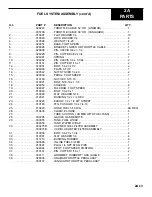
Page 31: ...2A PARTS FUEL SYSTEM ASSEMBLY 2A 12...

Page 32: ...8 024850 SHACKLE 2 19 024847 FULCRUM FOOT SPEED 1 20 010003 BOLT 1 4 20 x 1 2 21 010082 FLAT WASHER 5 16 2 22 012941 BUSHING 1 2 x 1 4 HEX 1 23 010220 ELBOW 1 4 x 1 4 90O STREET 1 24 010193 FTG PUSHLO...

Page 33: ...2A PARTS 2A 14 ELECTRICAL COMPONENTS...

Page 34: ...R LINAMAR 1 17 010091 LOCK WASHER 3 8 VANGUARDI ONLY 4 18 015684 NUT HEX 3 8 16 VANGUARD ONLY 4 19 038992 PLATE BATTERY MOUNT VANGUARD ONLY 1 20 036933 ROD BATTERY HOLDER VANGUARD ONLY 2 21 017751 FLA...

Page 35: ...2A PARTS 2A 16 VANGUARD WIRING DIAGRAM...

Page 36: ...3 5 034610 FIXTURE LIGHT 3 6 036771 DECAL TEMP 1 7 036770 DECAL CHARGE 1 8 036772 DECAL OIL 1 9 032125 SWITCH ROCKER 1 10 034876 DECAL LIGHTS 1 11 039005 PANEL CONTROL VANGUARD 1 12 029473 HOURMETER T...

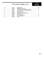
Page 37: ...2A PARTS 2A 18 PITCH CONTROL ASSEMBLY...

Page 38: ...AND THREADED ROD 1 3 015768 SOCKET HEAD CAP SCREW 1 4 20 X 1 4 2 4 029812 BUSHING SLIDE 1 5 015754 PIN SPIRAL 3 16 X 1 1 2 1 6 026420 ASSEMBLY TUBE AND PLATE 1 7 010036 BOLT 3 8 16 X 1 3 8 017751 FW...

Page 39: ...2A PARTS STEERING LEVER ASSEMBLY 2A 20...

Page 40: ...ALE 5 14 039678 NUT JAM HEX 1 2 20 6 15 026784 5 STEERING BAR 2 16 010464 NUT NYLON LOCK 3 8 16 6 17 017751 LOCK WASHER HDN 3 8 2 18 026234 SHAFT CONTROL LEVER MTG 1 19 026272 SHAFT FULCRUM ARM 1 20 0...

Page 41: ...2A PARTS SPRAY SYSTEM ASSEMBLY 2A 22...

Page 42: ...92 HOSE PUSHLOK 3 8 AS REQ 12 013392 HOSE PUSHLOK 3 8 AS REQ 13 013392 HOSE PUSHLOK 3 8 AS REQ 14 033735 PUMP F SPRAY SYSTEM 1 15 013392 HOSE PUSHLOK 3 8 VANGUARD AS REQ 16 037485 HARNESS WIRE F SPRAY...

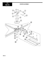
Page 43: ...2A 24 2A PARTS SPIDER ASSEMBLY...

Page 44: ...AGE 3 8 18 x 1 1 4 4 14 015682 LOCK WASHER EXTERNAL STAR 3 8 4 15 015686 SET SCREW SQ HEAD 3 8 16 x 1 4 16 015684 NUT JAM 3 8 16 8 17 026227 KEY 1 4 x 1 4 x 1 1 4 1 18 015690 WASHER RETAINING 1 19 015...

Page 45: ...8 18 RH 1 7 024984 PIVOT FOOT SPEED CONTROL 1 8 028018 LOCK POSITIVE PITCH 1 9 028035 LINK MASTER 35 2 10 028243 THROTTLE HD CABLE ASSEMBLY 1 11 028842 END CRUISE CONTROL CHAIN 1 12 028844 SIDE BRACK...

Page 46: ...010464 NUT NYLON LOCK 3 8 16 8 3 017751 FLAT WASHER 3 8 16 4 026729 DOLLY JACK MOUNTING TUBES FRONT 2 026728 DOLLY JACK MOUNTING TUBES REAR 2 5 026938 DOLLY JACK 2 7 024628 WHEEL SPACER 8 8 099014 TIR...

Page 47: ...cont d PRO 1200 RIDING TROWEL VINYL COVER PART 026595 1200 FLOATING DISCS PANS PART 026912 2 SET OF TWO LIFTING BRIDLE SLING TYPE PART 035461 TROWEL ARM ALIGNMENT JIG PART 016863 SPIDER PULLER ASSEMB...

Reviews: