background image

07/2014

Page 13

SECTION 2

OPERATIONS

Operations (cont’d)

Pre-start Checks

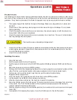
The following pre-start checks must be performed before the start of each work session or after every 
four hours of use, whichever is 

fi

 rst. Please refer to the Service and Maintenance section for detailed 

guidance. If any fault is discovered, the Plate Compactor must not be used until the fault is recti

fi

 ed.

1. 

Thoroughly inspect the machine for signs of damage, Make sure all guards are in place and    

 secured.
2. Check 

hoses, 

fi

 ller openings, drain plugs and other areas for signs of leakage. Fix any leaks    

 before 

operating.

3. 

Check the engine oil level and top up as necessary. Use proper engine oil with the proper vis-   


cosity (SAE 10W-30 is recommended).

4. 

Check the engine fuel level and top us as necessary. Use clean fuel. The use of contaminated   


fuel may damage the fuel system.

    This 

machine 

uses 

unleaded 

petrol/gasoline!!

5. 

Check the air 

fi

 lter is clean. Excessive dirt/dust accumulation within the 

fi

 lter element will cause  


erratic engine operation. Clean the air 

fi

 lter element when it is contaminated (refer to the Ser-   


vice and Maintenance section).

6. 

Check for fuel and oil leaks.

Start/Stop Procedure

1.  

Open the fuel cock.

2.  

Set the engine switch to the ON position.

3.  

Set the speed control lever to the STARTING position (Halfway between HIGH and LOW posi-   

 tion).
4.  

Move the choke lever to the CLOSED position.

5.  

Taking a 

fi

 rm hold of the Operating handle with one hand, grasp the recoil starter handle with the 


other, Pull the recoil starter handle until engine resistance is felt, then let starter return.

6.  

Taking care not to pull the starter rope fully out, pull the starter handle briskly.

7.  

Repeat until the engine 

fi

 res.

8.  

Once the engine 

fi

 res gradually set the choke lever to the OPEN position.

9.  

Let the engine run at idle for a few minutes to warm up.

10.   After the engine has warmed up, the machine is ready for operation.
11.  

Move the throttle lever to the high speed ‘H’ position quickly to prevent damage from occurring 


to the clutch. The ‘Full Throttle’ position of this machine has been preset at the factory to 


achieve optimum machine performance.

12.   With the engine running in the full throttle position, the machine will move forward and compact  
 loose 

‘lifts’.

13. 

In preparation for stopping the engine, move the throttle lever to the LOW position.

*Always follow manufacturer instructions*

*AAA Rent-All 225-291-1356*

Summary of Contents for ATC130H

Page 1: ...OPERATIONS PARTS MANUAL ATC130H ATC170H Gasoline Rammer Always follow manufacturer instructions AAA Rent All 225 291 1356...

Page 2: ...Always follow manufacturer instructions AAA Rent All 225 291 1356...

Page 3: ...EC assumes no responsibility or liability for any errors or inaccuracies that may appear in this manual Allen Products are covered under one or more of the following patent numbers U S Design Patents...

Page 4: ...r repairs made to the product without the written approval of Allen Allen specifically excludes from warranty any damage to any trowels resulting from an impact to the rotors 7 Impact damage is not co...

Page 5: ...aler Information 8 Ordering Parts 9 Section 1 Safety Safety Information 10 Section 2 Operations Machine Description 12 Pre Start Checks 13 Start Stop Procedure 13 Operation 15 Section 3 Service Servic...

Page 6: ...Case and Engine Assembly 22 ATC130H Guide Cylinder Spring Assembly 24 ATC130H Rammer Shoe Assembly 26 ATC170H Fuel Tank and Handle Assembly 28 ATC170H Gear Case and Engine Assembly 30 ATC170H Guide Cy...

Page 7: ...manual is divided into the following sections SECTION 1 SAFETY SECTION 3 SERVICE SECTION 2 OPERATIONS SECTION 4 PARTS Complete any warranty requirements as specified by the engine manufacturer in thei...

Page 8: ..._____ Additional Comments ______________________________________________________ ________________________________________________________________________ ______________________________________________...

Page 9: ...exact shipping instructions including the preferred routing and complete destination address 4 DO NOT return parts to AEC without receiving written authorization from AEC All authorized returns must...

Page 10: ...ner of this machine must observe and train the user to observe the effective laws of labour protection in the country of application Personal Protective Equipment PPE must be worn by the operator when...

Page 11: ...uelling DO NOT smoke or allow naked flames in the area Spilt fuel must be made safe immediately by using sand If fuel is spilt on your clothes change them Store fuel in an approved purpose made contai...

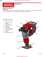
Page 12: ...nd footings It can also be used for repair work on streets highways and or pavements sidewalks ATC130H ATC170H 1 Oil Plug Site Glass 2 Engine 3 Throttle Lever 4 Operating Handle 5 Fuel Tank 6 Lifting...

Page 13: ...ce and Maintenance section 6 Check for fuel and oil leaks Start Stop Procedure 1 Open the fuel cock 2 Set the engine switch to the ON position 3 Set the speed control lever to the STARTING position Ha...

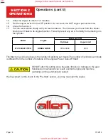
Page 14: ...into the cylinder The Max rpm as shown above is the number of ignitions per minute The number of ignitions per minute is different from the number of rotations of the engines Power Take Off Shaft DO...

Page 15: ...ing in a narrow trench if the ramming shoe should get caught between the walls of the trench the rammer may miss strike and can be severely damaged The ramming shoe may especially be damaged severely...

Page 16: ...tighten if necessary 2 Check and clean the air filter element re lube the element in accordance with the engine man ufacturer s recommendations If operating conditions are unusually dusty and severe f...

Page 17: ...880 mm Loosen three bolts at each side of the operating handles base and retighten them at the desired handle height Note that when the handle is set too high excessive vibration may be transmit ted...

Page 18: ...ll fuel tank 2 Fuel tap has been closed 2 Open fuel tap 3 Engine turned off 3 Turn engine ON 4 Contaminated damaged spark plug 4 Replace spark plug 5 Faulty carburetor 5 Service the carburetor Engine...

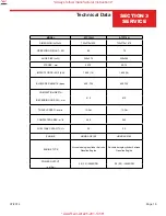
Page 19: ...S PER MINUTE bpm 650 700 650 700 COMPACTION DEPTH 610 610 DEPENDING ON SOIL mm TRAVEL SPEED m min 13 Oct 13 Oct COMPACTED AREA m h 260 260 FUEL TANK CAPACITY Ltr 3 5 3 5 ENGINE HONDA GX100 HONDA GX100...

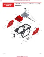
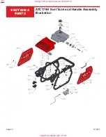
Page 20: ...07 2014 Page 20 SECTION 4 PARTS ATC130H Fuel Tank and Handle Assembly Illustration Always follow manufacturer instructions AAA Rent All 225 291 1356...

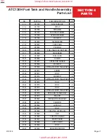
Page 21: ...1 15 061808 WASHER 3 01 16 061809 SPRING WASHER TANG ENDS 4 01 17 061810 SCREW 3 01 18 061811 BOLT 1 01 19 061812 WASHER 4 01 20 061813 SPRING WASHER TANG ENDS 20 01 21 061814 BOLT 2 01 22 061815 BOLT...

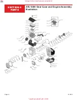
Page 22: ...07 2014 Page 22 SECTION 4 PARTS ATC130H Gear Case and Engine Assembly Illustration Always follow manufacturer instructions AAA Rent All 225 291 1356...

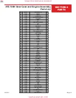
Page 23: ...EAR CASE 1 02 29 061859 O RING 1 02 30 061860 BOLT 2 02 31 061861 WASHER 1 02 32 061862 BEARING 1 02 33 061863 GEAR CASE 1 02 34 061864 BEARING 1 02 35 061865 CRANK GEAR 1 02 36 061866 CONNECTING ROD...

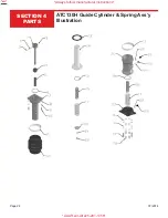
Page 24: ...07 2014 Page 24 SECTION 4 PARTS ATC130H Guide Cylinder Spring Ass y Illustration Always follow manufacturer instructions AAA Rent All 225 291 1356...

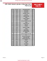
Page 25: ...0 061904 SCREW 8 03 11 061905 BELLOW HOOP 2 03 12 061906 BELLOW 1 03 13 061907 PACKING 1 03 14 061908 SPRING CYLINDER 1 03 15 061909 O RING 1 03 16 061910 INNER SPRING 2 03 17 061911 OUTTER SPRING 2 0...

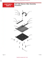
Page 26: ...07 2014 Page 26 SECTION 4 PARTS ATC130H Rammer Shoe Assembly Illustration Always follow manufacturer instructions AAA Rent All 225 291 1356...

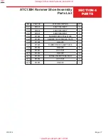
Page 27: ...5 SUNK HEAD BOLT 7 04 4 061926 RAMMER SHOE STEEL PLATE 1 04 5 061927 RAMMER SHOE WOODEN PLATE 1 04 6 061928 WASHER 1 04 7 061929 RAMMER SHOE CLAMP PLATE 2 04 8 061930 WASHER 6 04 9 061931 LOCK NUT 7 0...

Page 28: ...07 2014 Page 28 SECTION 4 PARTS ATC170H Fuel Tank and Handle Assembly Illustration Always follow manufacturer instructions AAA Rent All 225 291 1356...

Page 29: ...1 15 061950 WASHER 3 01 16 061951 SPRING WASHER TANG ENDS 4 01 17 061952 SCREW 3 01 18 061953 BOLT 1 01 19 061954 WASHER 4 01 20 061955 SPRING WASHER TANG ENDS 20 01 21 061956 BOLT 2 01 22 061957 BOLT...

Page 30: ...07 2014 Page 30 SECTION 4 PARTS ATC170H Gear Case and Engine Assembly Illustration Always follow manufacturer instructions AAA Rent All 225 291 1356...

Page 31: ...30 062463 BEARING 1 02 30 062464 INTERNAL CIRCLIP 1 02 31 062465 CRANK GEAR 1 02 32 062466 CONNECTING ROD 1 02 33 062467 BEARING 1 02 34 062468 EXTERNAL CIRCLIP 1 02 35 062469 INTERNAL CIRCLIP 1 02 36...

Page 32: ...07 2014 Page 32 SECTION 4 PARTS ATC170H Guide Cylinder Spring Ass y Illustration Always follow manufacturer instructions AAA Rent All 225 291 1356...

Page 33: ...10 062507 SCREW 8 03 11 062508 BELLOW HOOP 2 03 12 062509 BELLOW 1 03 13 062510 PACKING 1 03 14 062511 SPRING CYLINDER 1 03 15 062512 O RING 1 03 16 062513 INNER SPRING 2 03 17 062514 OUTER SPRING 2...

Page 34: ...07 2014 Page 34 SECTION 4 PARTS ATC170H Rammer Shoe Assembly Illustration Always follow manufacturer instructions AAA Rent All 225 291 1356...

Page 35: ...SHOE WOODEN PLATE 1 04 3 062528 RAMMER SHOE CLAMP PLATE 1 04 4 062529 WASHER 8 04 5 062530 LOCK NUT 8 04 6 062531 SUNK HEAD BOLT 8 04 7 062532 SUNK HEAD BOLT 2 04 8 062533 LOCK NUT 4 04 9 062534 SPRIN...

Page 36: ...URCE FOR CONCRETE EQUIPMENT 800 643 0095 or 870 236 7751 FAX 800 643 0097 or 870 236 3934 P O Box 819 Paragould Arkansas 72451 USA www alleneng com Always follow manufacturer instructions AAA Rent All...

Reviews: