background image

ASSEMBLY INSTRUCTIONS

7

5a.

6.

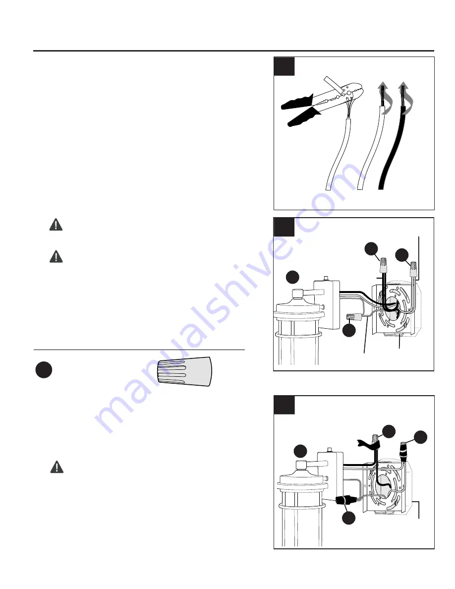
Unwrap BARE fixture wire from BLACK and WHITE 
fixture wires. Prepare wires by stripping 3/4 in. of 
insulation from wire ends using wire strippers (not 
included). 

Connect WHITE wire from fixture (A) to WHITE wire 
from outlet box using existing wire connector or wire 
connector (AA). Connect BLACK wire from fixture (A) 
to BLACK wire from outlet box using existing wire 
connector or wire connector (AA). 
Connect BARE/GREEN ground wire from outlet box 
to BARE ground wire from fixture (A) with wire 
connector (AA).  

NOTE:

 Screw wire connectors (AA) on in a clockwise 

direction.


WARNING:

 Never connect ground wire to 

WHITE or BLACK power supply wires.

      WARNING: 

To reduce the risk of fire, electrical 

shock or personal injury, wire connectors (AA) are 
designed to accept only one 12-gauge house wire 
and two lead wires from the light fixture. If your 
house wire is larger than 12-gauge or there is more 
than one house wire to connect to the corresponding 
fixture lead wires, consult an electrician for the 
proper size wire connectors to use.

Hardware Used

Wire Connector

  x 3

AA

Wrap electrical tape (not included) around 
each individual wire connector (AA) down 
to the wire. Push wire connectors (AA) 
gently back into outlet box. Carefully push 
excess wiring into outlet box. 


WARNING:

 Make sure no bare wire or 

wire strands are visible after making 
connections.

5a

5b.

6

5b

Outlet

Box

BLACK

WHITE

AA

AA

BARE/GREEN

A

A

AA

Outlet

Box

AA

AA

AA

Summary of Contents for WLL105BK

Page 1: ...66 439 9800 8 a m 6 p m EST Monday Thursday 8 a m 5 p m EST Friday 1 Purchase Date ATTACH YOUR RECEIPT HERE welcoming sophisticated inspiring allen roth is a registered trademark of LF LLC All Rights...

Page 2: ...reassembled to fixture A D Sensor 1 preassembled to fixture A E Sensor Cap 1 preassembled to sensor D F Rubber Washer 2 preassembled to mounting plate screw C Package Contents 2 Hardware Contents 3 Sa...

Page 3: ...ts if any of the fixture wires wire connections or splices were to become broken cut or loose during the mounting or normal operation of the fixture Under this condition anyone coming in contact with...

Page 4: ...on or electrical shock Note This device has been tested and found to comply with the limits for a Class B digital device pursuant to Part 15 of the FCC Rules These limits are designed to provide reaso...

Page 5: ...eginning assembly of product make sure all parts are present Compare parts with package contents list and hardware contents list If any part is missing or damaged do not attempt to assemble the produc...

Page 6: ...ox screws required for your outlet box are of a different size than the machine screws BB consult a licensed electrician before proceeding Use a level not included to adjust mounting plate B so mounti...

Page 7: ...ire to WHITE or BLACK power supply wires WARNING To reduce the risk of fire electrical shock or personal injury wire connectors AA are designed to accept only one 12 gauge house wire and two lead wire...

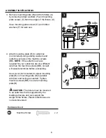
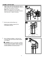
Page 8: ...ixture A adjust if necessary Restore power and test fixture A If lights do not function please refer to TROUBLESHOOTING 8 After completing installation caulk fixture A mounting surface with silicone w...

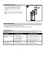
Page 9: ...g 2 Check all connections 1 Make sure power supply is ON 2 Check wiring and all connections 3 Contact customer service 4 Cap sensor or wait until dark 5 Remove sensor cap PROBLEM POSSIBLE CAUSE CORREC...

Page 10: ...All costs of installation and removal of the fixture is the responsibility of the consumer This warranty does not cover fixtures becoming defective due to misuse accidental damage or improper handling...

Reviews: