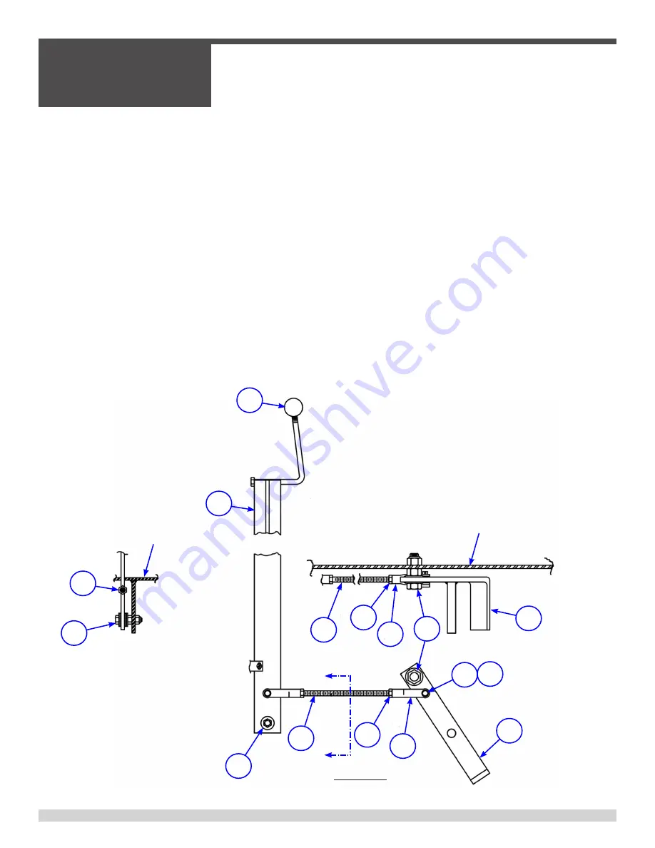
Dump Control Lever
A
A
SECTION A-A
REF. FRAME
7
3
2
1
8
7
4
10
9
9
5
6
4
7
8
3
REF. FRAME
SIDE VIEW
1) Console mounted dump control lever
Three (3) adjustments are possible: Position of foot pedal, drag on valve lever pivot, and drag on dump
pedal pivot.
1. Position of foot pedal: To readjust foot pedal position remove cotter pin (6) and clevis
pin (5) at
pedal. Loosen hex jam nut (7) and turn clevis (4) clockwise to lower pedal, counterclockwise to raise
pedal. Replace clevis pin (5) and cotter pin (6). Tighten hex jam nut (7).
2. Drag on valve lever (1) Pivot: This lever should return easily to neutral position. To change drag, loos-
en hex locknut on bolt assembly (3). Tighten hex nut to increase drag. Loosen hex nut to decrease
drag. Tighten locknut to 25-ft. lbs. Spray with lube after adjustment.
3. Drag on dump pedal pivot (9)t: same as adjustment 2 above except adjustment is made on bolt
assembly (10) and locknut is torqued to 120-ft. lbs. Spray with lube after adjustment.
4. Apply approved lubrication to all bucket dump lever points.
3.6 - Dump Lever Adjustment
SECTION 3
SERVICE
055838
Page 58
Summary of Contents for AW16-H
Page 16: ...INTENTIONALLY LEFT BLANK 055838 Page 16 ...
Page 17: ...Section 1 SAFETY 055838 Page 17 ...
Page 21: ...PAGE LEFT BLANK INTENTIONALLY SECTION 1 SAFETY 055838 Page 21 ...
Page 32: ...Notes SECTION 1 SAFETY 055838 Page 32 ...
Page 33: ...Section 2 OPERATIONS 055838 Page 33 ...
Page 36: ...2 2 Start up Procedures SECTION 2 OPERATIONS 055838 Page 36 ...
Page 45: ...Section 3 SERVICE 055838 Page 45 ...
Page 71: ...055838 Page 71 Section 4 ACCESSORIES ...
Page 72: ...4 1 Popular Accessories SECTION 4 ACCESSORIES 055838 Page 72 ...
Page 73: ...4 1 Popular Accessories SECTION 4 ACCESSORIES 055838 Page 73 ...
Page 74: ...PAGE LEFT BLANK INTENTIONALLY SECTION 4 ACCESSORIES 055838 Page 74 ...


