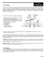
1.9 Operating
To utilize your Allen
®
Rider to its fullest capacity the machine should be driven in the direction the operator is
facing. This will finish the widest possible area while giving the operator an excellent view of the slab surface
about to be troweled. When the machine reaches the end of the slab make a 180 degree turn and repeat the
straight line of direction to the other end of the slab. To familiarize a new operator with the Riding Trowel the fol-
lowing steps should be taken.
1A
OPERATIONS
1A-10
A
B
D
E
F
G
H
2. With the operator in the seat, show him the functions of the control levers (B) and (C) and how to start the
machine. (refer to page 1A-9).
A hard level concrete slab with a little water on the surface is an ideal place for an operator to practice with the
machine. For practice, pitch the blades up approximately 1/4" on the leading edge. Start by making the machine
hover in one spot and then practice driving the machine in a straight line and making 180 degree turns. Best control
is achieved at full RPM.
CAUTION:
After starting engine, engage the throttle either 1/2 or fully. This allows the engine and the hydraulic fluid
to warm up faster. NOTE: If you start out at a low RPM this will cause the machine to have a slower response time
between movement of the joysticks and the rotors.
CAUTION: DO NOT
use excessive pressure on the joysticks. Excessive pressure does not increase the reaction
time of the machine and can damage steering controls.
1.10 Stopping
To stop the trowel's movement, allow the control levers (C) and (B) to return to their neutral position and release pres-
sure on the right foot pedal (E). You will need to push the engine throttle lever (I) towards the front of the machine.
This will reduce the speed of the engine. It is not recommended to leave the engine throttle lever in the rear posi-
tion if the rotors are not turning.
C
I
1. Point out the location of all operation components
A.
right pitch control (see illustration on next page)
B.
left control lever (forward reverse)
C.
right control lever (left & right, forward &reverse)
D.
left pitch control (see illustration on next page)
E.
right foot pedal (rotor control)
F.
left foot rest
G.
seat adjustment
H.
fuel gauge
I.
engine throttle lever
J.
engine coolant level


