SECTION 1
SAFETY
067975
Page 24
●
ALWAYS
keep the machine in proper running condition.
● Fix damage to machine and replace any broken parts immediately.
●
ALWAYS
store equipment properly when it is not being used. Equipment should be stored in a clean, dry location out of
the reach of children and unauthorized personnel.
●
DO NOT
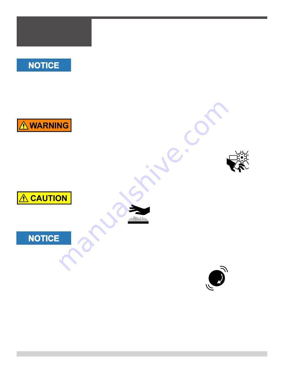
place hands or fingers inside engine compartment when engine is running.
●
NEVER
operate the engine with heat shields or guards removed.
● Keep fingers, hands hair and clothing away from all moving parts to prevent injury.
●
DO NOT
remove the engine oil drain plug while the engine is hot. Hot oil will gush out of the oil tank and severely scald
any persons in the general area of the screed.
●
NEVER
touch the hot exhaust manifold,
muffler or cylinder. Allow these parts to cool
before servicing equipment.
●
NEVER
run engine without an air filter or with a dirty air filter. Severe engine damage may occur. Service air filter frequent
-
ly to prevent engine malfunction.
●
NEVER
tamper with the factory settings of the engine or engine governor.
Damage to the engine or equipment can result if operating in speed ranges
above the maximum allowable.
General Safety (cont’d)
Summary of Contents for MP245
Page 1: ...OPERATIONS PARTS MANUAL MP245 RIDING TROWEL MANUAL PART 067975 I REVISION A ...
Page 2: ......
Page 13: ...067975 Page 13 Machine Dimensions 77 1 2 1968 5 54 1372 0 40 1 2 1029 1 2 68 5 40 1 2 1029 6 ...
Page 15: ...067975 Page 15 Engine Wiring ...
Page 18: ...SECTION 1 SAFETY 067975 Page 18 State Regulations Proposition 65 Warning ...
Page 19: ...SECTION 1 SAFETY 067975 Page 19 Federal Regulations Respiratory Hazards ...
Page 27: ...SECTION 1 SAFETY 067975 Page 27 Safety Labels and Decals cont d ...
Page 28: ...SECTION 1 SAFETY 067975 Page 28 Safety Labels and Decals cont d ...
Page 29: ...SECTION 1 SAFETY 067975 Page 29 Safety Labels and Decals cont d ...
Page 30: ...SECTION 1 SAFETY 067975 Page 30 Safety Labels and Decals cont d ...
Page 60: ...SECTION 4 PARTS 067975 Page 60 Seat Frame Assembly Illustration continued ...
Page 62: ...SECTION 4 PARTS 067975 Page 62 Front Screen Illustration ...
Page 64: ...SECTION 4 PARTS 067975 Page 64 Manifold Assembly Illustration ...
Page 71: ...SECTION 4 PARTS 067975 Page 71 PAGE LEFT BLANK INTENTIONALLY ...
Page 82: ...SECTION 4 PARTS 067975 Page 82 RH Rotor Assembly Illustration ...
Page 84: ...SECTION 4 PARTS 067975 Page 84 LH Rotor Assembly Illustration 050028 ...
Page 92: ...SECTION 4 PARTS 067975 Page 92 Hydraulic Schematic Illustration ...
Page 96: ...SECTION 4 PARTS 067975 Page 96 Electrical Wiring Harness Illustration 053206 ...
Page 97: ...SECTION 4 PARTS 067975 Page 97 Electrical Wiring Harness Illustration 053206 ...
Page 98: ...SECTION 4 PARTS 067975 Page 98 Cooler Wiring Harness Illustration 059546 ...
Page 99: ...SECTION 4 PARTS 067975 Page 99 Cooler Wiring Harness Illustration 059546 ...
Page 100: ...SECTION 4 PARTS 067975 Page 100 2 4 3 9 11 5 8 1 10 7 6 1 Dolly Jack Assembly Illustration ...


