4-40
053430; 1/11
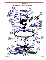
4.19 Parts List
Left Hand 20:1 Rotor Assembly
REF PART NO.
DESCRIPTION
QTY NOTES
-
064631
ASSY, LH 20:1 ROTOR
(1)
REF
1
037654
GEARBOX, 20:1 RATIO LH
1
2
029529
VALVE, RELIEF 1/8-27NPT (AIR V)
1
3
040794
ASSY, 1200-5-SHD LH SOM SPIDER
1
4
039686
CAP, SHD PRESSURE PLATE
1
5
039687
PLATE, SHD PRESSURE
1
6
039685
BEARING, THRUST AXIAL BALL EW
1
7
026215
ARM, YOKE
1
8
015678
PIN, YOKE ARM
1
9
015677
RING, Ø7/16 E-STYLE RETAINING
2
10
010513
FITTING, 1/4-28 STR GREASE
1
11
201163
FITTING, 1/8-27 PTF STR GREASE
1
12
015692
CAP, Ø1/4 RED GREASE
7
13
037652
WASHER, HD RETAINING
1
14
015691
SCREW, 1/2-13x1-1/2 RH SKT HD CAP
1
15
015693
PLUG, PLASTIC CAP EC12
1
16
040833
RING, 1200VG SD 5 BL STAB
1
17
025092
BUSHING, 3/8x1/2x5/16 BRONZE
5
18
025091
SCR, 5/16-18x1/2xØ3/8x3/8 SHLDR
5
19
026504
SCR, 5/16-18x1/2xØ3/8x1-1/4 SHLDR
1
20
012612
FSTN, NUT HEX NYLOCK 5/16-18
1
21
028778
BLADE, 8x18 FLAT FINISH GOLD
5
22
010090
WASHER, 5/16 SPLIT LOCK
15
23
010024
BOLT, 5/16-18x2 GR 5 HHCS
15
24
010095
WSHR, Ø5/8 ID ZINC SPLIT LOCK
8
25
020915
SCR, 5/16-11x1-1/2 HHC
4
26
029311
FSTN, HHCS 5/8-11 X 1 3/4 GR 8 YELLOW ZINC
4
27
010091
WSHR, Ø3/8 ID Z-STL SPLIT LOCK
4
28
010036
FSTN, HHCS 3/8-16 X 1
4
29
048966
WLDMNT, 2-WAY CROSSHEAD
1
30
011791
KEY, 1/4 SQ X 1 LG MACHINE
1
31
064632
WLDMNT, CROSSHEAD GEARBOX MOUNT
1
32
064210
STEERING ARM WMNT, LH
1
NOTES:
1.
Not shown.
Summary of Contents for MSP445
Page 1: ...OPERATIONS PARTS MANUAL MSP445 RIDING TROWEL REVISION 05 2018 MANUAL PART 053430 ...
Page 17: ...1 1 053430 01 11 Section 1 SAFETY Section 1 SAFETY ...
Page 29: ...2 1 053430 01 11 SECTION 2 OPERATIONS Section 2 OPERATIONS ...
Page 38: ...2 10 SECTION 2 OPERATIONS 053430 01 11 Notes ...
Page 39: ...3 1 053430 01 11 SECTION 3 SERVICE Section 3 SERVICE ...
Page 60: ...3 22 SECTION 3 SERVICE 053430 01 11 Notes ...
Page 61: ...4 1 053430 1 11 4 1 053430 1 11 Section 4 PARTS Section 4 PARTS ...
Page 74: ...4 14 053430 1 11 MSP445 Frame Pre 9 2013 048838 MSP445 Frame Post 9 2013 060891 Frame Design ...
Page 75: ...4 15 053430 1 11 4 6 Illustration Fuel System 1 2 4 5 8 9 10 11 11 10 12 13 6 7 14 ...
Page 77: ...4 17 053430 1 11 4 7 Illustration Electrical System 2 1 3 3 3 5 6 7 8 3 4 11 12 13 ...
Page 83: ...4 23 053430 1 11 4 10 Illustration Pitch Control Assembly 2 4 7 8 ...
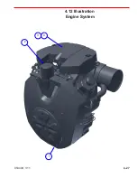
Page 87: ...4 27 053430 1 11 4 12 Illustration Engine System 1 2 3 4 ...
Page 91: ...4 31 053430 1 11 4 14 Illustration Driveline System 13 5 3 8 6 9 14 10 10 1 7 2 12 11 ...
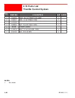
Page 93: ...4 33 053430 1 11 4 15 Illustration Throttle Control System 1 2 4 7 3 6 5 ...
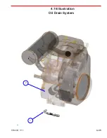
Page 95: ...4 35 053430 1 11 4 16 Illustration Oil Drain System 2 1 ...
Page 101: ...4 41 053430 1 11 4 20 Illustration Right Hand Spider Assembly 1 5 2 4 11 10 7 6 9 8 ...
Page 103: ...4 43 053430 1 11 4 21 Illustration Left Hand Spider Assembly 1 3 2 4 7 5 8 9 10 6 11 ...
Page 111: ...4 51 053430 1 11 4 25 Illustration Rear View Identification and Marking Decals 12 11 6 2 ...
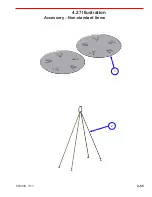
Page 115: ...4 55 053430 1 11 4 27 Illustration Accessory Non standard Items 2 1 ...
Page 117: ...4 57 053430 1 11 4 28 Illustration Tools Service 1 2 ...


